My marine intake came off a 2005 Mercruiser with a 305. I'll list what I did which worked as I've had it on two motors over the last four years without leaks or codes. It presently sits atop my 390 stroker. I'm not saying mine is the only or best way to do it only that it worked for me. First off though I started with an intake with all the brackets still on it which I re-purposed. I also have 24x so didn't need to mount the ICM which you will. That part should be pretty easy though.
(1) You need to drill and tap the hole for the ECM coolant temperature sensor. There's a boss for it in the MI lower same place as the L31 intake so it's easy. If I recall it's 3/8" NPT but may be 1/4".
(2) You need to drill a hole for the thermostat bypass and tap the end for a 3/8" NPT-5/8" hose barb 45 degree elbow. The old write-ups said to use 1/2" NPT-5/8" barb but a 3/8" NPT has the same inside diameter as a 5/8" hose barb so it's not a flow restriction. You also will likely breach the wall of the bypass channel boss in the manifold with the larger diameter. The old write-up regularly had folks patch the breaches with a tube insert and JB Weld probably because the drill size needed for the 1/2" fitting left too little metal. I did it carefully with an electric drill and straight edge and didn't have any issue with keeping it in the manifold boss so no tube and JB Weld for me. Trust me on this and no matter what anyone else may say stay with a 3/8" NPT which gives a 37/64" hole. The boss in the MI for the thermostat bypass channel is the same as it is for the L31.
(3) The upper plenum has two penetrations both having barbs: a very small one, 1/8" maybe, which will jumper to the pressure sensing port of the fuel pressure regulator and a larger one, maybe 3/8" which had a detachable rubber boot adapter to a 3/8" vacuum hose, which went to some kind of vacuum relay mounted on the manifold bracket. I repurposed this connection and hose for the canister purge solenoid (more later) and removed the relay using the bracket for it to anchor the electrical connector for the fuel injectors. There are two undrilled bosses in the upper, one in the middle one in the back end.
(4) There is a 5/8" hose barb fitting where the EGR manifold hose line lands in the L31 manifold. The barb fitting is held by red loctite so you'll need a torch to get it out. The port itself is 5/8" male inverted flare. If you buy into the argument that wondrous amounts of HP and fuel efficiency improvement accompanies an EGR delete and choose to go that route you can just plug it. I kept my EGR and purchased an EGR bracket for a 2001 Silverado 5.3L. This is the "divorced EGR" which you may be familiar with. It has 3/4" thin wall SST inlet and outlet which is an issue as the L31 uses the aforementioned 5/8". I used some 3/4"-5/8" male-male flare adapters which I purchased through Amazon as I couldn't find any other seller. They came in packages of 5 and came from Germany. Took three weeks to arrive. The L31 EGR hose line is about 2' long with the middle 1' smooth SST and the 6" on both ends spiral wound flexible SST. I cut this line in the middle of the smooth section, added a 5/8" flare nut, and flared the end of the half connected to the exhaust manifold. The front half going to the L31 manifold was discarded. The divorced EGR has some unique ends on both inlet and outlet. Both I cut off, installed 3/4" flare nuts, and flared. For the MI end I used one of the 5/8-3/4 adapters and ground off the male lip of the 5/8"end and used a 45 degree bur to feminize it to couple with the 5/8" male inverted flare port in the MI. installed it in the manifold and now it has a 3/4" standard male flare fitting coming out. The divorced EGR connected to the 3/4" end of each adapter and was the perfect length for being mounted just outside of the AC compressor bracket. I fabbed a mounting bracket for it from a 3.5" aluminum L bracket 1/4" thick from Online Metals which was something like $25 for a 1 ft length.
(5) The middle boss of the upper plenum mentioned above I drilled and tapped for as I recall a 1/2" NPT-1/2" hose barb which was used for the vacuum booster. I later plugged it when I swapped to hydroboost but at the time I still had the vacuum booster.
(6) The back boss of the upper plenum I drilled and tapped for a 1/4" NPT-3/8" hose barb for the PCV. I used a cheap Jegs billet aluminum PCV valve for the PCV port in the drivers side valve cover and tubing to the fitting in the manifold. It worked well for the L31 but the stroker was building up case pressure (KB pistons have a large ring gap which closes when hot but blowby when cold) and causing the rear main seal to leak. I swapped it out to a Wagner adjustable valve which fixed the issue. Those Wagner valves provide ALOT of case ventilation compared to standard PCV valves.
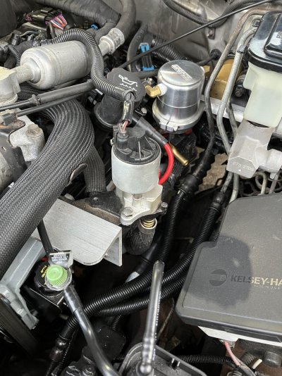
(7) I mounted the purge canister solenoid on a repurposed manifold bracket using some scrap from the EGR bracket I fabbed. I drilled and tapped for a 90 degree NPT to 3/8" hose barb fitting but don't recall the NPT size. I took the solenoid to Home Depot and Lowes trying all of their fittings until I found one at Lowes that gave a nice pop to the o-ring in the solenoid to prove a good fit. It was a standard size fitting but strangely only that one manufacturers elbow fit well. All others, stright or elbow, were either a little loose or a little tight.
(8) I used a Transdapt throttle body spacer to lift the throttle body enough that the cruise control arm wouldn't hit the fuel rail. Others say that they just bent the control arm a little to clear and that worked. The Transdapt spacer comes with two throttle body gaskets for both sides of the spacer which solves a problem that bending the cruise arm would still be present. The MI upper plenum needs a gasket but the L31 upper plenum uses a grooved ring. So if you don't use a spacer you'll need to get a gasket. the L29 throttle body gasket will work but it isn't a perfect fit. You'll have to trim it some or live with the excess that sticks out. Probably doesn't hurt and with the hood closed would look no different. But hood open would look hackish imho. Your truck your call.
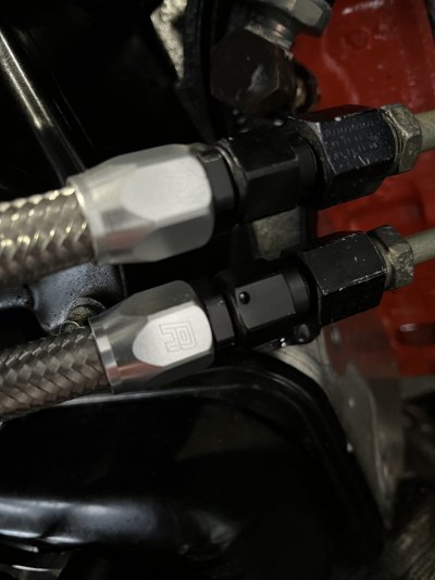
(9) Fuel lines will need to be fabbed for both supply and return. Distance is very short, maybe about 2" for both, with the return line being about 0.5" longer due to being higher on the manifold. You'll need some 6AN braided hose, a pair of 3/8" to 6AN hose adapters for the fuel line end, a M16-1.5 oring adapter (fuel line supply), a M14-1.5 oring adapter (fuel line return), a pair of 6AN 45 degree swivel hose end fittings for the manifold, a 3/8-6AN quick disconnect fitting (manifold fuel supply), and a 5/16-6AN quick disconnect fitting (manifold fuel return). Making up steel braided lines is a bit of a pita. It's not hard but a pita. If you can do it and not get steel splinters you're a far better craftsman than I am.
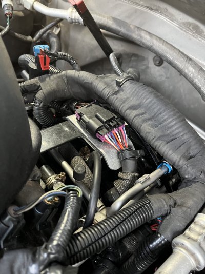
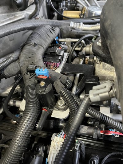
(10) For the injectors I made up all of the harnesses and ran them to a 16 pin metri-pack that I bought off ebay as a kit for something like $5. The injector harnesses were something like $30 which is robbery for what they are. I cut the wires to the spider terminal injector by injector and ran them to the metri-pack power (pink) wires on the bottom and color coded (ECM ground switching wire) on the top #1-#8 back to front. The wires were discolored due to age so I wanted to avoid crossing circuits by process rather than relying on wire color. There are better ways to do it that I have seen others post pictures of since I did mine but my way worked and it's easy.
(11) You can use the Bosch TMAP sensor for the MAP rather than swapping to a vortec MAP using an oring and bracket. Honestly I'm not sure why anyone ever went that way. The Bosch sensor is a 4 wire one though so you leave the T terminal unconnected. Power wire to power terminal, ground wire to ground terminal, signal wire to P terminal. There are conversion harnesses for doing this as the Bosch sensor, besides being generally superior to the vortec MAP, also has variants through 5 bar for boosters so apparently is in enough modified use to justify conversion harnesses. I bough one but ended up with the wrong vortec side connection so ended up cutting it off and splicing as a repair harness.
(12) You can use the same vortec water neck in the manifold and stock vortec radiator hose. The PPED write-up had them swapping to a TBI neck and hose which baffled me as to why they ever thought it to be necessary. The vortec neck clocks to the vortec position so use it as it is.
(13) Your FIs are Denso 24lb/hr standard which flow 27lb/hr at the vortec/MI 58psi. You can get these cheap through ebay and they are legitimate new Denso 24 lb/hr marketed to boat owners. Or use yours. I upgraded FIs when I put my stroker in using AC Delco 12613163 FIs which were used on flex fuel Malibu's and HHRs 2009-2012. These are 12 hole injectors which flow 41 lb/hr at 58psi and fit the MI perfectly at a cost to me of $17 each brand new (a lot of float in price though). Not saying you should change FIs to these just that there isn't much info any more on other FIs that work with the MI and I can affirm these work great for any others interested. Also, the 41 lb/hr isn't advertised anywhere. Only Scoggin Dickey had it right on flow but they didn't note the pressure. I ended up pulling the stock tune from a flex fuel HHR to get the flow.
(14) Treat the upper to lower manifold sealing ring with care. You can't get these anywhere and the vortec one can't be made to fit so if you lose or damage it you'll likely be using RTV in the future.