OEM Cluster Indicator questions - positive / negative

Disclaimer: Links on this page pointing to Amazon, eBay and other sites may include affiliate code. If you click them and make a purchase, we may earn a small commission.

jus10inbrla

I'm Awesome
Joined
May 26, 2018
Messages
1,198
Reaction score
1,032
Location
Baton Rouge
Its the third box. 1st is voltage in, 2nd voltage out, 3rd is current or amps.
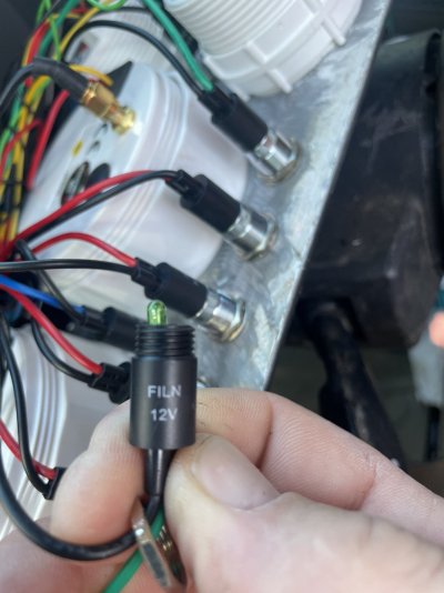
i meant on sellers info page. sorry for confusion. No instruction manual either. ive got an amp meter but its not reading anything.


may have found issue, im only getting 9v at the single brown wire into the alternator . So technicaly the indicator may be working properly??

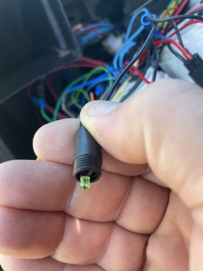
and of course since its 21° outside the plastic tab broke off when I unplugged it.. so now it just falls out .
 

Donald Mitchell

1990 C1500 5.7L
Joined
Sep 24, 2019
Messages
783
Reaction score
1,083
Location
Tennessee
I'm guessing your using a led 194 bulb. From what I found with a single led the current is about 0.05Amp. More chips will probably increase that. The calculator is asking for the current passing through the bulb while lit. If you can look up the bulb you used it would be more accurate.
 

Donald Mitchell

1990 C1500 5.7L
Joined
Sep 24, 2019
Messages
783
Reaction score
1,083
Location
Tennessee
That one probably has 2.2v and .05 amp. Also probably has resistor in that housing. Maybe someone else will chime in.
 

jus10inbrla

I'm Awesome
Joined
May 26, 2018
Messages
1,198
Reaction score
1,032
Location
Baton Rouge
Fwiw , from some of My testing this morning, i think the indicator is doing its job.… and the light is supposed to be on. The indicator is not “battery / alternator only” it can be anything, i put the symbol on the led.

once i get new alternator and complete the big 5 ground kit , i will revisit this.
 

jus10inbrla

I'm Awesome
Joined
May 26, 2018
Messages
1,198
Reaction score
1,032
Location
Baton Rouge
Hmmm see if yall make heads or tails of this answer… are they saying theres a built in 3k???
 

Attachments

  • C2B24AE0-7F2D-49FF-A72A-88B3816959C7.png
    C2B24AE0-7F2D-49FF-A72A-88B3816959C7.png
    460.4 KB · Views: 4

GoToGuy

I'm Awesome
Joined
Sep 16, 2020
Messages
3,158
Reaction score
3,716
Location
CAL
If you have instrument panel turn signals both lite up with when headlights are switched on you have a wiring fault somewhere.
Turn signals and brake lights are same circuit/ same bulb filament.
So when when headlights on, are brake/ turn , and dimmer taillight on , in back ,as would be at night stepping on brake?
Are you getting backfeed from instrument lighting grounds to turn signal indicators?
As I said before headlights and brake/ turn are different and separate circuits. Recheck your wiring move grounds.
If you want to do advanced electronic math and become an "Ohm's Law expert" rock on! Resistance for amperage not volts.
OR, just replace your turn signal relay, flasher with an Electronic unit. LED' s have vary little resistance that relates to amperage. A normal flasher operates with a bimetal contact. The amps flowing thru LED bulb have no chance to slow down and build resistance as would an incandescent bulb. That produces light by heating a filament, go ahead touch it! That same thing is happening in the flasher, gets hot then snap, cool down snap. On - off- on- off
LED a very little amp draw. Flasher does speak LED.
Easy fix, change to electronic flasher. Digital brain.
Good luck.
 

jus10inbrla

I'm Awesome
Joined
May 26, 2018
Messages
1,198
Reaction score
1,032
Location
Baton Rouge
It already has the electric flasher. I will check tonight to see if brake light on also when headlight on or just running light.

I have a strong suspicion its in the grounding, as when i was laying the circuits down one may have got crossed up
 

TonyM

I'm Awesome
Joined
Oct 15, 2020
Messages
163
Reaction score
376
Location
Canada
So putting a 330k resistor on wire 25 (pin a) did nothing, since its actually the return / negative

placed it onto 39 (pin f) resistor worked ; but dropped too much voltage . 12v in, 2.2v out. Not enough to illuminate led. Probably gona try some 100k.

@TonyM , did u put resistor on 25 or 39, and does the led still lite up at startup, go out on normal drving.. then illuminTe again when parameters are met to require it? What voltage was required to illuminate led, that will help some too
Not sure off hand which pin39 lites up, but to answer your other question all my leds light up with the key on, and turn off once the engine is running. Something tells me with my 100k resistors i actually had to bridge the + and - with the resistor for the park brake led to go completely out when the brake wasn't on.
 

Donald Mitchell

1990 C1500 5.7L
Joined
Sep 24, 2019
Messages
783
Reaction score
1,083
Location
Tennessee
Yep, without resistors between each front turn signal wire and ground you will get feedback. 6 ohm 50 Watt.
 
Last edited:
Top