Wiring issues

Disclaimer: Links on this page pointing to Amazon, eBay and other sites may include affiliate code. If you click them and make a purchase, we may earn a small commission.

MurderYurFace

Newbie
Joined
Sep 17, 2020
Messages
23
Reaction score
34
Location
Lexington, SC
Glad you were able to get the truck starting once again - progress is being made. Speaking of which,
can you get a clear picture of the wire that had been pinched between the engine & transmission? Or if unable to do that,
what is the color code of the formerly-pinched wire?

This may be an important clue as to which exact circuit was shorted and possibly lead us to the cause of the current
symptoms. One step at a time, and between the all of us we will outlast these electrical issues. (!)
Lol & I’m super glad to know for sure that I did the fuse box swap correctly. I was very intimidated by that particular task from start to finish ‍ but it had to be done
 

Road Trip

Supporting Member
Supporting Member
Joined
Jul 8, 2023
Messages
1,342
Reaction score
3,825
Location
Syracuse, NY
I also noticed that when I give it some throttle the rpm gauge doesn’t move. That’s not right, is it? Doesn’t the gauge get that reading from the CPS?

If we were troubleshooting the Mississippi River the CKP (CranKshaft Position) sensor would be
Lake Itasca, and your Tach would be New Orleans. But there's a little more to it.
:0)

Seriously, the path looks more like this: CKP > VCM > ICM > Coil > Tach. Check out this
big picture I grabbed from the '97 FSM:

You must be registered for see images attach


The book does a very job of explaining all this, but just to pique your interest here's a thumbnail sketch.

The signal from the CKP is referred to as "The Reference". IF the VCM isn't receiving a signal from the CKP = NO injector pulses + NO Ignition Timing Signal = NO Spark.

Good CKP > VCM = Ignition Timing Signal to ICM (Ignition Control Module), which in turn drives the primary side of the coil
via pulses. These power/no power pulses create the expanding/collapsing field generating the big KV sparks on the secondary
windings out to the dizzy, and eventually to the individual spark plugs in the firing order.

Guess what? Let's run a hypothetical across this circuit. Pin A of the coil is the constant +12v power from the ignition switch
when in the Start or Run positions. Pin C of the coil is actually the intermittent grounding of the primary coil by the ICM. (Grounding
= current flow = expanding magnetic field, while opening = no current flow = collapsing magnetic field.)

So what happens if the white wire to Coil Pin B (circuit #121) was the one that was pinched between the engine block and the
transmission bellhousing? A: This would ground out the primary side of the coil, effectively grounding out the ignition pulses
entering Pin C, so no expanding/collapsing of the magnetic fields across the secondary windings = no high voltage sparks at the
plugs = engine cranks over but otherwise no worky. And I'll bet you a dollar that the Tach was also reading zero rpm at the time.

Again, just one of many possible hypothetical scenarios based up your recent experience in your engine bay. Looking forward to
finding out which wire was actually pinched
during the transmission R&R...and we'll proceed from there.

Hope this quick overview gives you a better feel for who feeds who, from the CKP monitoring the rotation of your crank snout all
the way to your tach in the dash.

Continued Happy Hunting --
 
Last edited:

MurderYurFace

Newbie
Joined
Sep 17, 2020
Messages
23
Reaction score
34
Location
Lexington, SC
If we were troubleshooting the Mississippi River the CKP (CranKshaft Position) sensor would be
Lake Itasca, and your Tach would be New Orleans. But there's a little more to it.
:0)

Seriously, the path looks more like this: CKP > VCM > ICM > Coil > Tach. Check out this
big picture I grabbed from the '97 FSM:

You must be registered for see images attach


The book does a very job of explaining all this, but just to pique your interest here's a thumbnail sketch.

The signal from the CKP is referred to as "The Reference". IF the VCM isn't receiving a signal from the CKP = NO injector pulses + NO Ignition Timing Signal = NO Spark.

Good CKP > VCM = Ignition Timing Signal to ICM (Ignition Control Module), which in turn drives the primary side of the coil
via pulses. These power/no power pulses create the expanding/collapsing field generating the big KV sparks on the secondary
windings out to the dizzy, and eventually to the individual spark plugs in the firing order.

Guess what? Let's run a hypothetical across this circuit. Pin A of the coil is the constant +12v power from the ignition switch
when in the Start or Run positions. Pin C of the coil is actually the intermittent grounding of the primary coil by the ICM. (Grounding
= current flow = expanding magnetic field, while opening = no current flow = collapsing magnetic field.)

So what happens if the white wire to Coil Pin B (circuit #121) was the one that was pinched between the engine block and the
transmission bellhousing? A: This would ground out the primary side of the coil, effectively grounding out the ignition pulses
entering Pin C, so no expanding/collapsing of the magnetic fields across the secondary windings = no high voltage sparks at the
plugs = engine cranks over but otherwise no worky. And I'll bet you a dollar that the Tach was also reading zero rpm at the time.

Again, just one of many possible hypothetical scenarios based up your recent experience in your engine bay. Looking forward to
finding out which wire was actually pinched
during the transmission R&R...and we'll proceed from there.

Hope this quick overview gives you a better feel for who feeds who, from the CKP monitoring the rotation of your crank snout all
the way to your tach in the dash.

Continued Happy Hunting --
Wow…
Yea ima have to read all that a few more times to wrap my head around that haha
 

MurderYurFace

Newbie
Joined
Sep 17, 2020
Messages
23
Reaction score
34
Location
Lexington, SC
Hello again MYF,

We have yet to touch on this, but I decided to take quick look and see if we couldn't use your test
results to help illustrate how to troubleshoot an issue like this using the wiring diagrams in the FSM.

****

First of all, I decided that with my luck using a '99 manual to assist with your '97 vehicle just sets
us up to trip over any differences between the models. And navigating through electrical wiring
diagrams is already tough enough without further clouding the issue. So I've switched to using
the '97 FSMs, and I recommend that we standardize on them for this repair effort.

So the first thing I wanted to find out was more about the BAT fuse. From previous experience I
know that on the '96+ models the Battery is first connected to the Underhood Fuse & Relay block
prior to being fed to the IP fuse block & elsewhere.

So I needed to know which fuse in the Underhood Fuse Panel is the 'BAT'?

You must be registered for see images attach


So the Battery Fuse looks to be in position #7. (Keep this in the back of your mind for the next diagram.)


So when I'm working an electrical issue, I always like to start at the page where the battery is drawn,
and trace the circuit all the way from there. So here's the first page where I found both the 12v
battery as well as the BATTERY fuse:

You must be registered for see images attach


Putting these 2 diagrams together, now when you unplug/plug the BATTERY fuse in the Underhood
Fuse Block now you can see which fuses downstream in the (in cab) I/P fuse panel are involved in the
parasitic drain you discovered.

Don't know as of yet whether the draw is a feature or a fault. Once you track the current draw down to a
specific I/P fuse or specific electrical load we'll have a better idea. Possibly at some point down the road
we will decide to switch from a test light to quantifying the size of the current drain with a multimeter.

But the point is, if we treat the wiring diagrams like a road map, then since we're primarily dealing with
straightforward +12v DC we should be able to get this figured out.

By the way, while we are here I'd like to take a little mystery away from the way these wiring diagrams
are marked up. For example, the wire coming from Battery Fuse #7 has "5 Red 142" written next to it.

The '5' is the size of the wire in metric-speak, the Red is the color to look for, and 142 stands for unique
electrical circuit #142. Having spent a lifetime working with classic wire gauge numbering, if you tell me
to look for a 16 gauge wire vs a 4 gauge wire, I can easily visualize one is a lot larger than the other.

By the same token, I still have difficulty with taking a metric size & being able to visualize it. For me,
the attached translation table is a huge help when I'm reading the wiring diagram and trying to find
the matching physical wire in the vehicle.

****

No doubt at the outset that all this looks to be a huge grind, but once you fix a couple of electrical
issues and start to get the hang of navigating through the diagrams it's not nearly as bad as it
initially seemed.

One last thing. No worries about how you tested the headlight bulb. It just means that all we
need to do is verify that +12v is being sent to the bulb connector, and also verify a near-zero
resistance between the ground pin on the bulb connector and G113.

Best of luck with your hunt.
Looking into that first chance I get tomorrow!
 

MurderYurFace

Newbie
Joined
Sep 17, 2020
Messages
23
Reaction score
34
Location
Lexington, SC
If we were troubleshooting the Mississippi River the CKP (CranKshaft Position) sensor would be
Lake Itasca, and your Tach would be New Orleans. But there's a little more to it.
:0)

Seriously, the path looks more like this: CKP > VCM > ICM > Coil > Tach. Check out this
big picture I grabbed from the '97 FSM:

You must be registered for see images attach


The book does a very job of explaining all this, but just to pique your interest here's a thumbnail sketch.

The signal from the CKP is referred to as "The Reference". IF the VCM isn't receiving a signal from the CKP = NO injector pulses + NO Ignition Timing Signal = NO Spark.

Good CKP > VCM = Ignition Timing Signal to ICM (Ignition Control Module), which in turn drives the primary side of the coil
via pulses. These power/no power pulses create the expanding/collapsing field generating the big KV sparks on the secondary
windings out to the dizzy, and eventually to the individual spark plugs in the firing order.

Guess what? Let's run a hypothetical across this circuit. Pin A of the coil is the constant +12v power from the ignition switch
when in the Start or Run positions. Pin C of the coil is actually the intermittent grounding of the primary coil by the ICM. (Grounding
= current flow = expanding magnetic field, while opening = no current flow = collapsing magnetic field.)

So what happens if the white wire to Coil Pin B (circuit #121) was the one that was pinched between the engine block and the
transmission bellhousing? A: This would ground out the primary side of the coil, effectively grounding out the ignition pulses
entering Pin C, so no expanding/collapsing of the magnetic fields across the secondary windings = no high voltage sparks at the
plugs = engine cranks over but otherwise no worky. And I'll bet you a dollar that the Tach was also reading zero rpm at the time.

Again, just one of many possible hypothetical scenarios based up your recent experience in your engine bay. Looking forward to
finding out which wire was actually pinched
during the transmission R&R...and we'll proceed from there.

Hope this quick overview gives you a better feel for who feeds who, from the CKP monitoring the rotation of your crank snout all
the way to your tach in the dash.

Continued Happy Hunting --
Ok I’ve circled back around to the BATT circuit from the fuse box being the main culprit. However I’m still unable to find that particular circuit on the half dozen wiring diagrams that I scanned & printed from my chilton manual. All of the wires coming out the fuse box are orange lol every single one.
So I got my test light bridging bw the negative terminal & the negative post, it’s glowing bright red. I remove the 50 amp BATT fuse, light goes out. Ok… so now what should I do? My wiring diagrams aren’t really helping me any & I am pretty sure I understand how to read them, it’s really not that hard I just cannot find the BATT circuit on any of them & therefore do not have a clue what color to look for or where to look. I think a ‘wiggle’ test would be my next best option but I wanted to see what you guys have to say abt it.

Also, I have power @ the OBD2 port. My scan tool comes on but it won’t communicate with the ECU. No engine coolant temp on the gauge. No RPM on the gauge. No CEL either. All interior lights work but the ac blower motor doesn’t come on when I turn the knob.
There’s so much going on I don’t know how to wrap my head around it smh

But it IS running so there’s that. However I have to disconnect the MAF sensor to make it start for some reason. Good lord I thought these trucks were supposed to be easy?
 

Schurkey

Supporting Member
Supporting Member
Joined
Jan 14, 2018
Messages
11,693
Reaction score
14,872
Location
The Seasonally Frozen Wastelands
You've verified ALL the fuses, ALL the fusible links, and ALL the circuit breakers?

No doubt someone will tell you to verify ALL the grounds, too.
 

Road Trip

Supporting Member
Supporting Member
Joined
Jul 8, 2023
Messages
1,342
Reaction score
3,825
Location
Syracuse, NY
Ok I’ve circled back around to the BATT circuit from the fuse box being the main culprit. However I’m still unable to find that particular circuit on the half dozen wiring diagrams that I scanned & printed from my chilton manual. All of the wires coming out the fuse box are orange lol every single one.

Sir,

In order for us to get unstuck on this wiring issue, we have to make the decision to use the very best
electrical wiring harness documentation out there for a GMT400 platform like yours. And based upon serious
data omissions like the one you have discovered, the Chilton Manual simply isn't up to the task. We will need
to set that aside and instead make full use of the '97 Factory Service Manual.

****

Before posting a page from the aforementioned FSM, here's a quick overview of the power layout in the '96+ GMT400s.

1) The battery is the headwaters of the whole shebang. Anywhere from ~600 to 1000 Cold Cranking Amps can be
delivered instantaneously to a load, and the total quantity of power delivered is limited only by the internal resistance of
the load itself.

And if that load is a wire where the insulation has finally chafed to bare wire against frame, then a serious safety hazard exists.
Not just sparks and fire, but arc-welding levels of power. Serious stuff.

So to help prevent a car fire hazard, a tight web of fusible links, fuses, and even circuit breakers are installed throughout
the vehicle to minimize the chances of you hitting a big pothole & suddenly a chunk of the wiring harness goes up Chernobyl style.
Instead, when a serious short occurs, all that happens is either a fuse, breaker, or fusible link opens, killing the circuit, and
inconveniencing the driver as opposed to what Rainman would definitely put on the 'serious injury' list.

2) As a GMT400 troubleshooter, the good news is that the majority of these safety devices have been concentrated in 2 distinct
locations: The Underhood Fuse/Relay block near the brake master cylinder, and the I/P (Instrument Panel) fuse block
in the cab.

In the Underhood Fuse Block the circuits are mostly powertrain-centric, and also they are ahead of the Ignition Switch,
so they are "Hot At All Times". (And marked this way in the electrical wiring diagrams.) Note that some of the fuses in
the Underhood Fuse Block in turn feed fuses in the I/P fuse block. Please keep this in the back of your mind for later.
Note: There is a variety of fuse ratings in the Underhood Fuse block, but the higher amperage ones will only be found
in this fuse block. And one visual hint that I'm working with a feed from the Underhood Fuse Block is that the 'Hot at
All Times' wires are color-coded RED.

3) As we all know from living with these machines, a few functions are always available, (Horn, Headlights, dome light, etc)
...but at the same time there are many electrical circuits only available when the driver has enabled their use via choosing
a specific position to turn the Ignition Key.

In turn, most (but not all) circuits in the I/P fuse block are AFTER the ignition switch, so they will be marked as

* Hot in ACC & Run
* Hot in Run only
* Hot in Start & Run
* Hot in Start (only)

And only the smaller fuse sizes and amperages are found in the I/P fuse block. NOTE: Both fuse blocks have overlapping
fuse number locations, so it's easy for confusion to occur when reading the prints. Always double-check to see which fuse
block the fuse is installed in.

And when dealing with "Hot at All Times" wires from the I/P fuse block, they are typically color-coded ORANGE.

****

I know, we're covering pretty basic stuff in the above, but I want us to be reading the following page from the same
perspective. I've taken the following from the '97 FSM, and here's what Chilton's didn't include:


You must be registered for see images attach

(NOTE: MAXI Fuse #7 = BATTERY Fuse thanks to equivalence table previously listed in Reply #22)

Check out the color coding of all the wires coming out of the Underhood Fuse block.
And then look at the color coding of all the wires coming out of the I/P fuse block.

IF the battery is connected, they are all still 'Hot At All Times', even if the key is out of the ignition.
You know, we often get complacent when working on wiring that's after the Ignition Switch. But
in this area you really need to remember to disconnect your battery before any real wiring harness
maintenance commences.

****

Troubleshooting Time. After all the coloring & sparky-splaining, it looks like the BATTERY fuse in the
Underhood Fuse block fans out to feed the Stop-Haz, PWR ACCY CIRCUIT BREAKER, and T CASE fuses.

With any luck, by pulling these 3 fuses, one of them will remove the parasitic current draw, and then you can
put a tighter focus on the bad circuit. That would be a best-case scenario.

IF the parasitic draw is still present after these 3 fuses are pulled, then one of 2 scenarios remain:

* A chafe/short condition in Circuit #142 between the Underhood & I/P fuse blocks, traversing
Pin A7 of C100 and splice S200.

* Circuit #142 is OK, but your test light stays on until you methodically depopulate the I/P fuse block and
finally get the light to extinguish. NOTE that it could be more than 1 fuse involved, depending
upon the scope of the wiring error. (This would be a worst-case scenario.)

****

That's all I got at this point. My hope is that you are able to further narrow down this parasitic draw to a
single circuit in the I/P fuse block, and we can then dig further into the wiring diagrams and go from there.

Q: Does this make sense? And if you haven't already done so, please take advantage of the FSMs for
your truck that are a free download over HERE. Note: The '97 manuals are listed separately in one of
the replies to this thread. It's where I got what I used here.

Let us know what you find.

Best of luck --

EDIT: I've included a clean copy of the '97 Power Distribution page in .pdf format so that you can
easily blow up the details and better follow the wiring diagram during your troubleshooting session.
 

Attachments

  • '97 Power Distribution page.pdf
    750.3 KB · Views: 5
Last edited:

MurderYurFace

Newbie
Joined
Sep 17, 2020
Messages
23
Reaction score
34
Location
Lexington, SC
Sir,

In order for us to get unstuck on this wiring issue, we have to make the decision to use the very best
electrical wiring harness documentation out there for a GMT400 platform like yours. And based upon serious
data omissions like the one you have discovered, the Chilton Manual simply isn't up to the task. We will need
to set that aside and instead make full use of the '97 Factory Service Manual.

****

Before posting a page from the aforementioned FSM, here's a quick overview of the power layout in the '96+ GMT400s.

1) The battery is the headwaters of the whole shebang. Anywhere from ~600 to 1000 Cold Cranking Amps can be
delivered instantaneously to a load, and the total quantity of power delivered is limited only by the internal resistance of
the load itself.

And if that load is a wire where the insulation has finally chafed to bare wire against frame, then a serious safety hazard exists.
Not just sparks and fire, but arc-welding levels of power. Serious stuff.

So to help prevent a car fire hazard, a tight web of fusible links, fuses, and even circuit breakers are installed throughout
the vehicle to minimize the chances of you hitting a big pothole & suddenly a chunk of the wiring harness goes up Chernobyl style.
Instead, when a serious short occurs, all that happens is either a fuse, breaker, or fusible link opens, killing the circuit, and
inconveniencing the driver as opposed to what Rainman would definitely put on the 'serious injury' list.

2) As a GMT400 troubleshooter, the good news is that the majority of these safety devices have been concentrated in 2 distinct
locations: The Underhood Fuse/Relay block near the brake master cylinder, and the I/P (Instrument Panel) fuse block
in the cab.

In the Underhood Fuse Block the circuits are mostly powertrain-centric, and also they are ahead of the Ignition Switch,
so they are "Hot At All Times". (And marked this way in the electrical wiring diagrams.) Note that some of the fuses in
the Underhood Fuse Block in turn feed fuses in the I/P fuse block. Please keep this in the back of your mind for later.
Note: There is a variety of fuse ratings in the Underhood Fuse block, but the higher amperage ones will only be found
in this fuse block. And one visual hint that I'm working with a feed from the Underhood Fuse Block is that the 'Hot at
All Times' wires are color-coded RED.

3) As we all know from living with these machines, a few functions are always available, (Horn, Headlights, dome light, etc)
...but at the same time there are many electrical circuits only available when the driver has enabled their use via choosing
a specific position to turn the Ignition Key.

In turn, most (but not all) circuits in the I/P fuse block are AFTER the ignition switch, so they will be marked as

* Hot in ACC & Run
* Hot in Run only
* Hot in Start & Run
* Hot in Start (only)

And only the smaller fuse sizes and amperages are found in the I/P fuse block. NOTE: Both fuse blocks have overlapping
fuse number locations, so it's easy for confusion to occur when reading the prints. Always double-check to see which fuse
block the fuse is installed in.

And when dealing with "Hot at All Times" wires from the I/P fuse block, they are typically color-coded ORANGE.

****

I know, we're covering pretty basic stuff in the above, but I want us to be reading the following page from the same
perspective. I've taken the following from the '97 FSM, and here's what Chilton's didn't include:


You must be registered for see images attach

(NOTE: MAXI Fuse #7 = BATTERY Fuse thanks to equivalence table previously listed in Reply #22)

Check out the color coding of all the wires coming out of the Underhood Fuse block.
And then look at the color coding of all the wires coming out of the I/P fuse block.

IF the battery is connected, they are all still 'Hot At All Times', even if the key is out of the ignition.
You know, we often get complacent when working on wiring that's after the Ignition Switch. But
in this area you really need to remember to disconnect your battery before any real wiring harness
maintenance commences.

****

Troubleshooting Time. After all the coloring & sparky-splaining, it looks like the BATTERY fuse in the
Underhood Fuse block fans out to feed the Stop-Haz, PWR ACCY CIRCUIT BREAKER, and T CASE fuses.

With any luck, by pulling these 3 fuses, one of them will remove the parasitic current draw, and then you can
put a tighter focus on the bad circuit. That would be a best-case scenario.

IF the parasitic draw is still present after these 3 fuses are pulled, then one of 2 scenarios remain:

* A chafe/short condition in Circuit #142 between the Underhood & I/P fuse blocks, traversing
Pin A7 of C100 and splice S200.

* Circuit #142 is OK, but your test light stays on until you methodically depopulate the I/P fuse block and
finally get the light to extinguish. NOTE that it could be more than 1 fuse involved, depending
upon the scope of the wiring error. (This would be a worst-case scenario.)

****

That's all I got at this point. My hope is that you are able to further narrow down this parasitic draw to a
single circuit in the I/P fuse block, and we can then dig further into the wiring diagrams and go from there.

Q: Does this make sense? And if you haven't already done so, please take advantage of the FSMs for
your truck that are a free download over HERE. Note: The '97 manuals are listed separately in one of
the replies to this thread. It's where I got what I used here.

Let us know what you find.

Best of luck --

EDIT: I've included a clean copy of the '97 Power Distribution page in .pdf format so that you can
easily blow up the details and better follow the wiring diagram during your troubleshooting session.
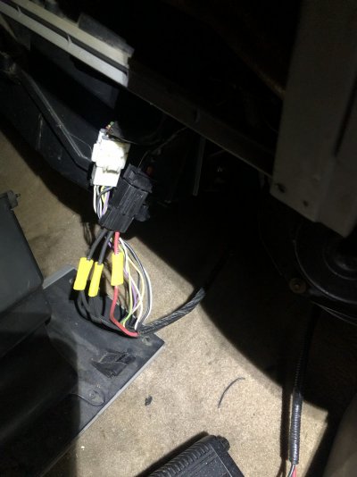
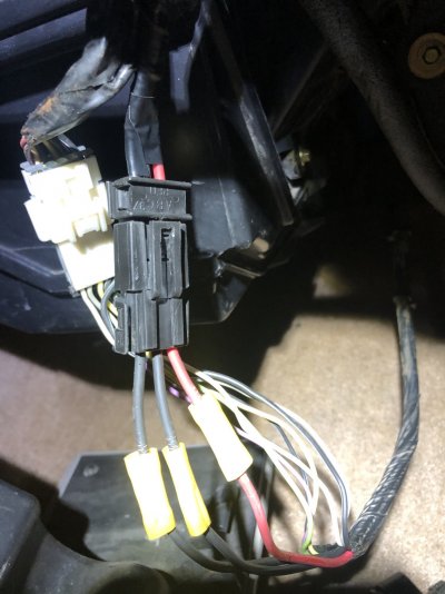
Quick update for you guys: I traced one of the shorts to a connector underneath the dash behind the glove box. It’s the black one in the attached picture. I can’t remember where I set the crispy one down but it was pretty bad. Only problem is after fixing it, the electrical issues seem to have only gotten worse. Now when I turn on my headlights, the trucks idle slows down a little bit & the voltage needle drops a little as well. For some reason my Speedo gauge is dancing. & I also noticed that occasionally when i turn the key to the ACC position, the service engine soon light doesn’t illuminate. & then later I’ll go to test something again & it’ll come on lol smh

This is driving me crazy!

The headlight/wiper issue is still there. All the time, no chill AT ALL. Lol

& I have verified with test light bw the neg terminal & neg post that there is in fact a short somewhere in the Transfer Case circuit. I just haven’t investigated that one yet.

Hope everyone is having a good night. I’m turning in.
 

Attachments

  • IMG_2593.jpeg
    IMG_2593.jpeg
    245.8 KB · Views: 5
  • IMG_2592.jpeg
    IMG_2592.jpeg
    221.5 KB · Views: 5

MurderYurFace

Newbie
Joined
Sep 17, 2020
Messages
23
Reaction score
34
Location
Lexington, SC
Quick update for you guys: I traced one of the shorts to a connector underneath the dash behind the glove box. It’s the black one in the attached picture. I can’t remember where I set the crispy one down but it was pretty bad. Only problem is after fixing it, the electrical issues seem to have only gotten worse. Now when I turn on my headlights, the trucks idle slows down a little bit & the voltage needle drops a little as well. For some reason my Speedo gauge is dancing. & I also noticed that occasionally when i turn the key to the ACC position, the service engine soon light doesn’t illuminate. & then later I’ll go to test something again & it’ll come on lol smh

This is driving me crazy!

The headlight/wiper issue is still there. All the time, no chill AT ALL. Lol

& I have verified with test light bw the neg terminal & neg post that there is in fact a short somewhere in the Transfer Case circuit. I just haven’t investigated that one yet.

Hope everyone is having a good night. I’m turning in.
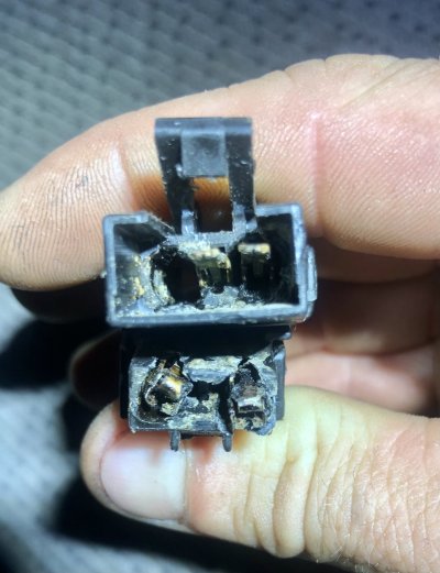
I found the ‘crispy connector’. Posting pic just for show & tell. Someone pls help me lol
 

Attachments

  • IMG_2595.jpeg
    IMG_2595.jpeg
    227.8 KB · Views: 3

docstoy

I'm Awesome
Joined
May 8, 2024
Messages
178
Reaction score
106
Location
Kentucky
You have been given some very good instructions on how to locate your problems . You have to look at your problems 1 circuit at a time and not get side tracked by everything else going on . You need to concentrate on using the wiring diagrams as your source of information , if you enable a circuit whether it be with a fuse or a connection look at wiring diagrams to see and verify what is on that circuit and that it operates or functions . If something else is enabled or working that shouldn't be stop and re'ck your circuit to make sure you don't have anything else that's causing your problem . Look at the little picture and not the big picture . If something is happening that shouldn't be stop back up and re'ck your work so far . Get that fixed first !!! Then go on to the next problem . Remember 1 circuit at a time !!! Don't panic , YOU are the one that is there and are the eyes and ears for everyone else that is trying to help you . If you get stuck re'read the post so far to make sure you have not overlooked anything and the wiring diagrams along with your test light and hopefully dvm and scanner are your tools . Again 1circuit at a time and don't panic , you can figure this out !!!
 
Top