TBI rebuild

Disclaimer: Links on this page pointing to Amazon, eBay and other sites may include affiliate code. If you click them and make a purchase, we may earn a small commission.

tsr2185

I'm Awesome
Joined
Oct 2, 2020
Messages
284
Reaction score
206
Location
New Iberia, LA
I have been reading along this thread. Doing a rebuild of my tbi, exhaust manifold gaskets,and intake gasket. 95 7.4 L never been touched except for tune up parts. Thinger 2 is correct. Start with the basics, get the engine running as it should then do some modifications. I have been a Caterpillar diesel mechanic for 30 yrs, it is always best to go back to square one if you are chasing a problem. Just keep at it and you will find the issue. At least you are trying to do the work yourself instead of giving up and paying someone else to fix it. You don't learn anything by just sitting on the couch reading the internet. You got to get your hands dirty, scrap a few nuckles. Lol.
best of luck.
Hoping I dont have a bad head gasket. I've head that's a possibility but a leakdown would confirm. If all else fails I'll end up buying a leakdown kit. Just want this engine 100% so I can start working on interrior and exterior! I havent even washed or cleaned the inside since I got it 9 months ago....
 

studigggs

I'm Awesome
Joined
Feb 19, 2018
Messages
260
Reaction score
330
Location
CA
I'm just another guy trying to do things I shouldnt be doing on a truck lol..

Hell, mechanics in my town won't even work on my 1990...Most techs weren't even born when these were around. You are doing it right. We've all learned the same way you are.
 

Schurkey

Supporting Member
Supporting Member
Joined
Jan 14, 2018
Messages
11,379
Reaction score
14,433
Location
The Seasonally Frozen Wastelands
Assuming the timing marks are accurate, and the timing light is accurate, if the timing light shows 0 when connected to #1 or #6 plug wire = initial timing is 0, and therefore correct.

There's multiple positions the distributor can be in, and still have the initial timing correct.

All but one of those positions will look screwy, including looking like someone played Pin-The-Tail-On-The-Distributor. However, it will function just fine if the plug wires are routed accordingly, and don't cross-fire.

SOME distributor housings could affect oil flow if turned too far away from "stock". But the timing would be correct if the timing light shows it to be correct.


Oh, yeah. One more thing. The spark should not ground through the battery, the firewall, or the frame rail. The spark is created by the collapse of the magnetic field in the ignition coil windings. So the high-tension, secondary windings of the coil are both the starting and ending point of the "spark" (voltage surge.) Ideally, the spark grounds from plug, to head, to intake manifold, to distributor housing, to ignition coil. If the circuit is any more involved than that, you're just adding more complexity without any benefit.

"Waste spark" ignitions are even more simple--the spark travels from coil to plug wire, to plug. Across the gap from center electrode to side electrode. To the head, to the companion plug, to the side electrode. Across the gap of the companion plug, to the center electrode, to the plug wire, to the other terminal on the same ignition coil. Which is why they sell "double platinum" plugs, because half the plugs fire from side to center electrode and half fire from center to side electrode; and it's easier to put platinum on both than sell plugs with platinum only on the side electrode, and plugs with platinum only on the center electrode, and then expect people to put the correct plug in the correct cylinder based on ignition coil polarity.
 
Last edited:

tsr2185

I'm Awesome
Joined
Oct 2, 2020
Messages
284
Reaction score
206
Location
New Iberia, LA
Assuming the timing marks are accurate, and the timing light is accurate, if the timing light shows 0 when connected to #1 or #6 plug wire = initial timing is 0, and therefore correct.
Still worth the effort to assume my dizzy is not crazy off, and the TDC on cyl 1 correlates with 0 on the HB, correct? It's a PITA to pull plugs and mess with all that especially if it doesnt fix the issue. But like thinger said I needa restart at the basics. And the new dizzy is the very first thing I did to get the truck running and havent messed with it since...

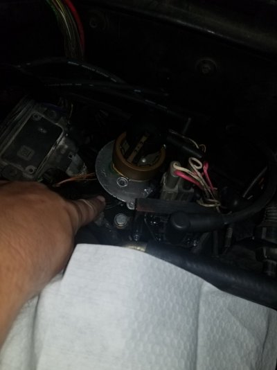
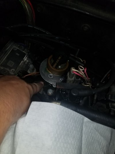
Notice how the # 1 on the cap (disregard the wire numbers, I dodnt remember the correct order at the time) is pointed directly forward instead of towards #1 cylinder? This makes me think I definitely skipped a few gears when I reinstalled new one?

You must be registered for see images attach
 
Last edited:

Erik the Awful

Supporting Member
Supporting Member
Joined
Aug 9, 2019
Messages
7,992
Reaction score
16,584
Location
Choctaw, OK
"Waste spark" ignitions are even more simple--the spark travels from coil to plug wire, to plug. Across the gap from center electrode to side electrode. To the head, to the companion plug, to the side electrode. Across the gap of the companion plug, to the center electrode, to the plug wire, to the other terminal on the same ignition coil.
In my experience, wasted spark simply refers to the opposing cylinder firing during the exhaust str0ke. Back in my rotary engine days, we'd completely bypass the distributor on the leading ignition so that both rotors sparked at the same time whenever the coil fired. We used two coils in parallel. Can you explain how the distributor would get the spark back to the coil through one center post?
 

tsr2185

I'm Awesome
Joined
Oct 2, 2020
Messages
284
Reaction score
206
Location
New Iberia, LA
Back to basics bud.
Pull the plugs,
Turn the crank untill you find TDC on number one either by sticking a plastic straw or a screwdriver or whatever into the plug hole.
TDC on the cpmpression ****** on number one.
Then look at the timing mark on the crank.
It should be at zero
The old school point the dist at number 1 doesnt really work on a TBI.
Look inside the dist.
You want the pointy parts to line up.
Ill get into that later if you need it
When you look at info on the web.
Make sure you are only looking at TBI info and not just generic chevy 350 info.
Same applies to any site.
Always look at TBI specific info and not ******** from somebody who sells scanners or doesnt even own a TBI.
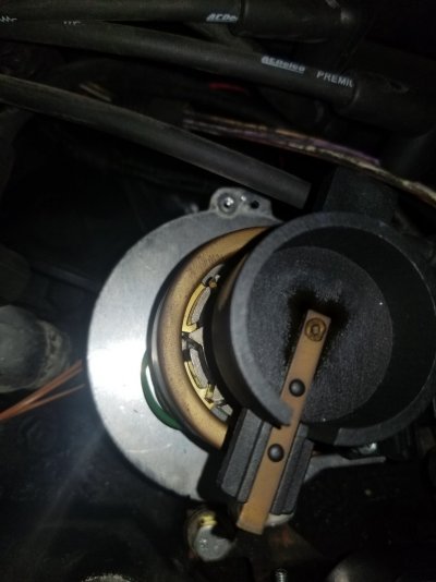
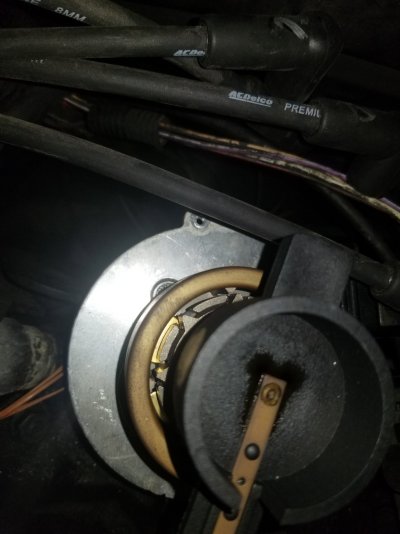
Pull plug #1 and used a breaker bar with my compression guage in cyl 1. As soon as I saw pressure I pulled guage and put straw in. I can barely feel it but seemed like piston 1 was at its peak, looked at HB and the 0 was pretty damn close. I put it to 0 and pulled my cap and saw the rotor was facing towards plug 1. It is oriented way more clockwise than the original I believe. Pictures below. How do the pointy things look to you? Should I pull dizzy and reseat at a better orientation?? Rotor was damn near pointing to cyl 2.
 

Attachments

  • 20210818_091929.jpg
    20210818_091929.jpg
    133.7 KB · Views: 7
  • 20210818_091935.jpg
    20210818_091935.jpg
    174.4 KB · Views: 7
  • 20210818_091940.jpg
    20210818_091940.jpg
    190.7 KB · Views: 6

tsr2185

I'm Awesome
Joined
Oct 2, 2020
Messages
284
Reaction score
206
Location
New Iberia, LA
Back to basics bud.
Pull the plugs,
Turn the crank untill you find TDC on number one either by sticking a plastic straw or a screwdriver or whatever into the plug hole.
TDC on the cpmpression ****** on number one.
Then look at the timing mark on the crank.
It should be at zero
The old school point the dist at number 1 doesnt really work on a TBI.
Look inside the dist.
You want the pointy parts to line up.
Ill get into that later if you need it
When you look at info on the web.
Make sure you are only looking at TBI info and not just generic chevy 350 info.
Same applies to any site.
Always look at TBI specific info and not ******** from somebody who sells scanners or doesnt even own a TBI.
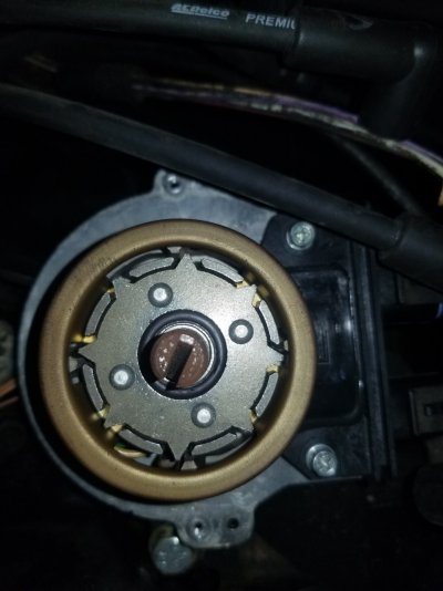
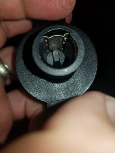
Mo better pictures. Seems like the pointy things dont line up? Also the rotor just snaps on??? I would think that's just a bad connection waiting to happen...
 

Attachments

  • 20210818_111413.jpg
    20210818_111413.jpg
    198.7 KB · Views: 8
  • 20210818_111420.jpg
    20210818_111420.jpg
    178.4 KB · Views: 8

Schurkey

Supporting Member
Supporting Member
Joined
Jan 14, 2018
Messages
11,379
Reaction score
14,433
Location
The Seasonally Frozen Wastelands
In my experience, wasted spark simply refers to the opposing cylinder firing during the exhaust str0ke. Back in my rotary engine days, we'd completely bypass the distributor on the leading ignition so that both rotors sparked at the same time whenever the coil fired. We used two coils in parallel. Can you explain how the distributor would get the spark back to the coil through one center post?
"Waste spark" uses a single ignition coil with twin output terminals, to fire spark plugs in two cylinders at the same time--one on the exhaust ******.

Oh for ****'s sake--what sort automotive forum won't allow the word "str_oke"?

You're describing a rotary engine system using parallelled components. Not exactly the same thing, since the rotary engine geometry never has a spark plug in the exhaust position.

How bout this photo pointing to plug 1.
I'll have to go out and look at my truck.
Mo better pictures. Seems like the pointy things dont line up?
The timing is not at "0" degrees, if the pointy things don't line up at TDC.

Also the rotor just snaps on??? I would think that's just a bad connection waiting to happen...
All the rotor has to do is turn, and insulate the rotor shaft. A friction-fit to the shaft is fine.

I've had those rotors so tight on the shafts (rusted spring clip) that the rotor plastic had to be broken to get it removed.
 
Top