New marketplace truck, most of the electric does not work.

Disclaimer: Links on this page pointing to Amazon, eBay and other sites may include affiliate code. If you click them and make a purchase, we may earn a small commission.

Road Trip

Supporting Member
Supporting Member
Joined
Jul 8, 2023
Messages
1,117
Reaction score
3,184
Location
Syracuse, NY
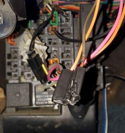
Happy Halloween folks! I come bearing good news! That is (what is left) of my radio harness! For some reason known only to god, the ground was cut out of it. I put a ring connector on and bolted it to the dash and suddenly my gauges seem to read mostly correct AND both power windows work again AND my HVAC screen has come back on and I can hear relays clicking around in the dash. The blower motor doesn't seem to want to come online but I'm sure it's connected to another bad ground.

Making progress - good news!

Current issues now are:

When using the dimmer slider, at lowest brightness the gauges read correct, at anything past that, they read all crazy.

Check this out. In the following ground distribution drawing, you will see that both both the dimmer circuit AND the
the IP (Instrument Panel) share the same ground! Your symptoms match the documentation:

EDIT: Notice that the factory radio also shared this ground. We're getting pretty close to the scene of the accident...

(Taken from p.91 of '90 CK Wiring manual)
You must be registered for see images attach


Your symptoms indicate that you now have a shared marginal ground situation. When you turn the dimmer lights
up, the extra current causes a voltage drop across the ground, thereby causing a
brownout condition for the gauges in the Instrument Cluster. (See above.)

According to the manual, here is where G202 was originally installed on the assembly line:
You must be registered for see images attach

(From p. 135 of the '90 CK Wiring manual)

Alright, back in '90 the ALDL connector was used by GM. This was superceded by the OBD2
connector in the '95-'96 timeframe.

To minimize the variables, if you haven't already done so, put G202 back to it's original position.
And with a bit of fine sandpaper (180/220/etc) make every metal interface between the
mount > ground ring connector > washer > screw shoulder nice & shiny. And install the
screw securely.

And IF we still have an issue, then you need to go back to S207 (Splice 207) and make sure that
it isn't a marginal interconnect as well.

Again, although there are still issues, the symptoms match the documented ground distribution
fanout, so we on the right track. (!)

Please make all this so, and report back with your findings.
 
Last edited:

Road Trip

Supporting Member
Supporting Member
Joined
Jul 8, 2023
Messages
1,117
Reaction score
3,184
Location
Syracuse, NY
The blower motor doesn't seem to want to come online but I'm sure it's connected to another bad ground.

I decided to dig into the symptom that the blower motor is not working. On page 71, I found the following:

(Detail from p. 71 of the '90 CK Wiring manual)
You must be registered for see images attach

Note: Blower motor ground path is: C214 > S218 > C209, pin B > S207 > G202 (!)

In English, pretty much all the symptoms you mentioned in your last post are related to G202.


You're getting close!
 
Last edited:
Joined
Oct 7, 2023
Messages
19
Reaction score
35
Location
Saint Louis
I decided to dig into the symptom that the blower motor is not working. On page 71, I found the following:

(Detail from p. 71 of the '90 CK Wiring manual)
You must be registered for see images attach

Note: Blower motor ground path is: C214 > S218 > C209, pin 150 > S207 > G202 (!)

In English, pretty much all the symptoms you mentioned in your last post are related to G202.


You're getting close!
This is absolutely stunning. Again, best forum experience I've ever had. Can I give you beer money or something??

Now, I have a scary feeling that g202 is gonna be missing wires or just missing entirely. What would be the best plan of action in that case? Trace every black wire and put them together and make a new G202? Almost scarier is if G202 is still there and completely in tact. We'll cross that bridge when we get to it.
 

Road Trip

Supporting Member
Supporting Member
Joined
Jul 8, 2023
Messages
1,117
Reaction score
3,184
Location
Syracuse, NY
This is absolutely stunning. Again, best forum experience I've ever had. Can I give you beer money or something??

Don't want to jinx the fix -- I don't want to start spraying the champagne around 'til we regain positive control over
this flaky electrical system. But so far, so fun...I'm getting some much-needed practice navigating the General's
wiring diagrams.

Now, I have a scary feeling that g202 is gonna be missing wires or just missing entirely. What would be the best plan of action in that case? Trace every black wire and put them together and make a new G202? Almost scarier is if G202 is still there and completely in tact. We'll cross that bridge when we get to it.

I know what you mean. This is the 'peering over the edge of the volcano' phase of a large-scale
electrical troubleshooting session. This is always the moment where I sincerely hope that I don't
snatch defeat from the jaws of victory. Especially in public. :0)

To answer your question, if it was me I would absolutely trace/inventory each & every ground wire, and
if necessary rebuild a new G202 ground circuit as documented. Lots of bright, well-compensated engineers
designed/tested/reviewed the circuit, so I am predisposed to respect that. (In other words,
I *will* modify a circuit, but only when I can clearly state why it would be smart to do so. A perfect example
would be to upgrade your headlights after the fact to a low voltage drop 'headlight switch drives headlight relay'
setup as you & Schurkey were kicking around earlier.)

Again, in this case I'd carefully assess what you have under your dash, compare that to the schematics,
and make G202 a solid circuit. (Quite obviously it can single-handedly mess with the cab's electrical
behavior.)

You know what? The fact that you observed that the dimmer circuit (by actually brightening the lights)
drove the gauges wonky is a solid indicator that we are on the right track. As I'm fond of saying, You can't
fix an intermittent until you can first figure out how to break it at will. Which you have succeeded in doing.

Take your time. Make those grounds as shiny/pristine as the situation allows. If the flakiness is gone, Great!
If we still have issues, we will just continue to work through them methodically until we run out of stuff to fix.

Cheers --
 
Last edited:
Joined
Oct 7, 2023
Messages
19
Reaction score
35
Location
Saint Louis
WE'RE BACK! Kinda. Wanted to take a picture but boy is it cramped under the dash. G202 was completely disconnected and tucked into the wiring coming out of the back of the fuse block. Why? Only god and the previous owner know. Reconnected it and I now have turn signals and a blower motor, AND nice hot heat; it's getting to be in the 20s in Missouri and I'm not upset about having heat again. Slight complaint is that the blend door is probably missing so it comes out of every vent, but HVAC is HVAC

Now, my gauge cluster still goes wacky with the dimmer slider, using the turn signals makes it go crazy too with the gauges all moving up and down in sync with the flasher. My CTSY fuse is still always on, but I wonder if that has something to do with that melted orange and black melted connector dangling in there.

I can't get access to S207 unless I remove my dash which I am not entirely willing to do, honestly. This is where I'm once again considering adding new grounds to the back of the cluster and to my dimmer/headlight switch OR putting in some pod gauges and calling it a month. Especially with all my outside lights now functioning properly.
 

Road Trip

Supporting Member
Supporting Member
Joined
Jul 8, 2023
Messages
1,117
Reaction score
3,184
Location
Syracuse, NY
...G202 was completely disconnected and tucked into the wiring coming out of the back of the fuse block. Why? Only god and the previous owner know. Reconnected it and I now have turn signals and a blower motor, AND nice hot heat; it's getting to be in the 20s in Missouri and I'm not upset about having heat again.

...Especially with all my outside lights now functioning properly.

Great news -- finding/reconnecting G202 is another major step forward towards the goal!

The symptoms all pointed to G202 being marginal. (And it was marginal despite being
completely disconnected by this ground circuit backfeeding through one of the devices
all interconnected via Splice S207.)

Shared grounds backfeeding when the primary connection is disturbed is why ground issues can cause
such weird symptoms. (On the other hand, since we divvy up the delivery of positive power through
dedicated fuses, when we have an issue there the side effects are automatically finite/limited in scope.)

****

I'm researching the melted 2-conductor connector, and also looking into where you can run a fresh
new ground wire from the Instrument Panel back to G202. (Effectively bypassing a suspect ground
path between the Instrument Panel & S207.) More shortly.

****

From over here in upstate NY it looks like we're rapidly approaching the line where your truck goes
from having showstopper electrical issues (no blower in winter, exterior lights malfunctioning, etc)
to having nuisance issues that we'd like to sort out as long as it doesn't take xx hours or $$$ to fix?

In English, we will eventually get to the point where you will run the risk/reward calculation and decide
to let the remaining electrical 'personality' be. I like to think of it as functional patina. (ie: Truck starts
every day without fail, but the radio won't remember any station presets...but none of the local radio
stations are worth remembering? :0)

But let's see how far we can fix this without resorting to heroics like pulling the entire dash.

Good job! :waytogo:
 
Last edited:

Road Trip

Supporting Member
Supporting Member
Joined
Jul 8, 2023
Messages
1,117
Reaction score
3,184
Location
Syracuse, NY
I found a melted connector, 2 wire orange and black, sitting near a footwell light, underneath the OBD port. Can't seem to find anything it connects to though.

At first glance, I was having trouble getting that melted connector to match
up with anything in the '90 C/K wiring diagram?

But after studying the photo closely, it looked like the camera flash skewed/slightly
washed out the color coding of the wires? So I imported your photo, used the color correction
function (it can automagically compensate for the color spectrum skew of the light source)
& added just a bit of saturation, an ended up with this:

Toasted 2 prong connector with Orange & Brown wires connected.
You must be registered for see images attach

Note: Compare Brown wire to Black wire running horizontally behind it.

Armed with this insight, I found that there is a 2 prong Connector (C207) listed on
p. 89, in the upper left hand corner, with an Orange & Brown wire to it. It's for
the 4-way Hazard Flasher! (See below.)


You must be registered for see images attach


And according to the Component Locator, C207 and the Hazard Flasher are located
in the vicinity of where you discovered that toasted connector:

(P.136, '90 C/K Wiring Manual)
You must be registered for see images attach

Note: #3 is Hazard Flasher, shown plugging into C207.)


Finally, to make sure that I wasn't barking up the wrong tree, I looked up a Hazard Flasher for
a '90 C1500, and found this:

You must be registered for see images attach


I think we're got an answer for that dangling connector.

Q: Are your 4-way emergency flashers currently operating?

Check it out & let us know what you find. Here's hoping we're one step closer to
unwadding that underdash wiring harness.

Cheers --
 

Attachments

  • Toasted 2 prong connector(flash washout corrected).jpg
    Toasted 2 prong connector(flash washout corrected).jpg
    65.3 KB · Views: 11
Last edited:
Joined
Oct 7, 2023
Messages
19
Reaction score
35
Location
Saint Louis
At first glance, I was having trouble getting that melted connector to match
up with anything in the '90 C/K wiring diagram?

But after studying the photo closely, it looked like the camera flash skewed/slightly
washed out the color coding of the wires? So I imported your photo, used the color correction
function (it can automagically compensate for the color spectrum skew of the light source)
& added just a bit of saturation, an ended up with this:

Toasted 2 prong connector with Orange & Brown wires connected.
You must be registered for see images attach

Note: Compare Brown wire to Black wire running horizontally behind it.

Armed with this insight, I found that there is a 2 prong Connector (C207) listed on
p. 89, in the upper left hand corner, with an Orange & Brown wire to it. It's for
the 4-way Hazard Flasher! (See below.)


You must be registered for see images attach


And according to the Component Locator, C207 and the Hazard Flasher are located
in the vicinity of where you discovered that toasted connector:

(P.136, '90 C/K Wiring Manual)
You must be registered for see images attach

Note: #3 is Hazard Flasher, shown plugging into C207.)


Finally, to make sure that I wasn't barking up the wrong tree, I looked up a Hazard Flasher for
a '90 C1500, and found this:

You must be registered for see images attach


I think we're got an answer for that dangling connector.

Q: Are your 4-way emergency flashers currently operating?

Check it out & let us know what you find. Here's hoping we're one step closer to
unwadding that underdash wiring harness.

Cheers --
4 ways are inoperable, so that makes sense. Really makes you wonder why that connector of all things would be melted. At some point I suppose I'll go to the junkyard and clip off a not melted connector and get those going again. Thank you! I did some thinking last night and while my knowledge of wiring is very little, I couldn't come up with a reason why I couldn't clip the grounds coming off the plug for both IP and dimmer and isolate them. Worst case it would do nothing, best case it works as intended?
 

Road Trip

Supporting Member
Supporting Member
Joined
Jul 8, 2023
Messages
1,117
Reaction score
3,184
Location
Syracuse, NY
4 ways are inoperable, so that makes sense. Really makes you wonder why that connector of all things would be melted. At some point I suppose I'll go to the junkyard and clip off a not melted connector and get those going again. Thank you!
|

The 4-way flashers not working confirms what we have managed to piece together between
your photos and the '90 C/K Electrical Service Manual. Yes!

As for why the heat damage, it will have have been caused one of the following:

* Vibration over the years loosening the electrical connections between the flasher and C207?
(This would then require an extended 4-way flashing session for some unknown reason to turn the
loose connection into a heat source?)

* Possibly a malfunction inside the original flasher turned it into a quiet, non-clicking miniature space heater?
Given that the normal flash flash flash function naturally limits the duty cycle (on time) inside the unit, if the
flasher were to mechanically fail in a 'stuck heating' position, then much more heat than normal
would occur per unit time. Possibly enough to heat damage Connector C207?

Check out this video where the guy removes all the mystery on how exactly these old flashers actually work:


xc_hide_links_from_guests_guests_error_hide_media


So, the short answer is that these old electromechanical marvels actually work by generating heat
internally on purpose. And a savvy owner would always listen for the familiar
clicking sound, and if the clicking stopped, you would return the flasher switch/button
to the Off position & investigate why? Because if you don't, and leave the hazard flasher button
ON, and the flasher gets stuck in the 'heat' (vs. conduct) cycle, the external lights never flash,
but the little flasher just sits there and bakes itself?

Your recovery plan to go to the treasure yard and getting another connector with no
signs of thermal stress is a good one. Optimist Road Trip thinks that an untoasted treasure yard
connector and a fresh flasher may solve this issue outright.

And Pessimist Road Trip would interject that IF by installing a new flasher & connector we end up with a
different symptom further down this circuit then we'll just worry about that when the time comes. (ie: Chafed wire
to one of the bulbs, more current than expected, but not enough to blow the upstream fuse, etc. Again, this
would require an extended 4-way flasher session to set up this Goldilocks failure window?)

In English, an electrical possibility, but a much lower probability. Methinks a cheap aging flasher failed, PO was
oblivious to the fact that it wasn't working, and this allowed the little bugger to leave it's mark on the way out.
:0)

****

The silver lining in this troubleshooting exercise is that as we continue to track down & eliminate these electrical
gremlins, the remaining ones stand out in bold relief and become easier to figure out/fix.

I did some thinking last night and while my knowledge of wiring is very little, I couldn't come up with a reason why I couldn't clip the grounds coming off the plug for both IP and dimmer and isolate them. Worst case it would do nothing, best case it works as intended?

Agreed. Since the dimmer function is actually working as expected, the symptoms would suggest that we
first clip the ground wire to the IP, and install a new wire from there back to G202. This may well solve
the gauge readings being affected (by logically unrelated) turn signal or illumination-related current flows.

But if that doesn't work, then I wouldn't hesitate to try giving the dimmer circuit it's own ground path too.
Certainly won't hurt.

I'll share the specifics on this area in the next post.

Dude, this is the very essence of sweat equity via relentless electrical circuit troubleshooting.
When you are done you will have actually earned the use of a truck returned to reliable operation by
being willing to put in the necessary time and troubleshooting under the dash.

Meanwhile, there's students just starting out on their EE degree paying good money to learn
pretty much the exact same thing. It's either a free working truck, or free tuition for a
working knowledge of the electrical system in your truck. Your perspective is your choice! :)
 
Last edited:

Road Trip

Supporting Member
Supporting Member
Joined
Jul 8, 2023
Messages
1,117
Reaction score
3,184
Location
Syracuse, NY
...I did some thinking last night and while my knowledge of wiring is very little, I couldn't come up with a reason why I couldn't clip the grounds coming off the plug for both IP and dimmer and isolate them. Worst case it would do nothing, best case it works as intended?

When you attempt to get the gauges to not react to the dimmer & the turn signals, here's
the info from the '90 Wiring Manual so that you know which wire is the ground wire to target:

(IP ground path= C201, Pin '150' > Black wire > Splice 207 > Black Wire > G202)
You must be registered for see images attach


FWIW I attached a couple of photos just to give you an idea of what this IP connector is
going to look like once you get the cluster removed. And like you said substituting a new
dedicated ground wire from C201 to G202 will best-case fix the symptom, or worst case
do no harm.

Edit: There is also the "Panel & Interior Lamps Control Switch" on this page in case you
want to inspect/test/bypass the ground in this area.

Good luck, and let us know what you end up with --
 

Attachments

  • moonie gauge cluster backside view.jpg
    moonie gauge cluster backside view.jpg
    262.5 KB · Views: 13
  • '90 IP connector (88-91 OBS Chevy Moon Gauges to 92-94 Needle Gauge swap).jpg
    '90 IP connector (88-91 OBS Chevy Moon Gauges to 92-94 Needle Gauge swap).jpg
    132.4 KB · Views: 14
Last edited:
Top