Good stuff here, I'll reply to various segments:
Exactly. Those meters weren't designed to measure milliohms using their "Ohms" resistance capability.
Yes, but (of course) this is best done when carrying high load in the conductor (e.g., 100A thereabouts). Measuring under no- or low-load isn't really the objective. Measurements can be done not only to the charge wire but any significant wire, e.g., ground lead to battery, ground strap(s), power lead to the fuse block, fuel pump power and ground, headlight power and ground, etc. When in doubt about how heavily the conductor's loaded, I'll measure using a DVM (to get the voltage drop in the conductor) and a DC current clamp (to get the current flow); from these one can determine, in general, whether there's a concern and, if useful, the resistance (R = V/I) of the conductor.
Defining "big" would help here. "Big" to me is, generally, a voltage drop of .3V or less when under the heaviest load for that conductor. That's "generally". I would tune that number up or down in specific situations.
Yes, that's not a bad example, but I don't know if that picture was taken under load. 0.03V would be very good IMHO if the current in that ground lead was 100A.
In the case of 100A... sure, OK, allowable but could do better by a few tenths... if one really wants / needs the incremental improvement that, say, 0.2V might bring (which isn't much but could make the difference in a few, atypical situations).
I'm not exactly sure what you mean by this, "ground changing" and what's meant by "stays OK", but I'll let it slide unless you want to comment.
Yes... No... I would do it from cable endpoint to cable endpoint, unless... if the cable has a connector in its midpoint, I would measure twice (treating it as though it was two cables, effectively).
OK, I cry fowl. How much is "a lot" and how much is "some"?

I've said "under load, .3V" or less. If greater, think about the situation and whether improvement is possible (my not be) and beneficial (if not, don't bother).
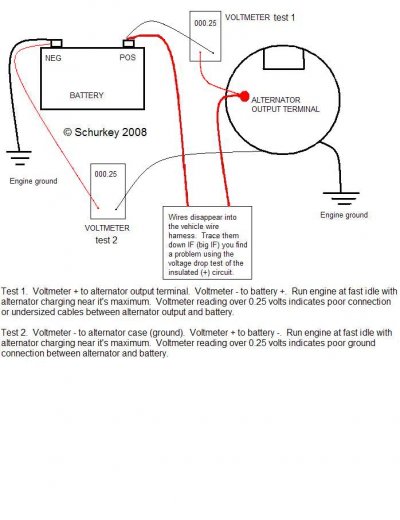
Yup. Use the alternator's "voltage sense" option carefully. It's a neat feature but if used without care it can cause large voltages in the wrong place.
Example: In my K1500 the alternator (B+) lead runs to the battery and then continues on (across the radiator) to the driver's side fuse block. I've considering running a "voltage sense" wire from that fuse block connection back to the ALT, but it could be a bad idea.
Why? If large loads are present at the fuse block and cause notable voltage drop in that conductor (~1V say), the voltage at the battery will be higher than optimal; if the loads are present for a long period of time, the higher voltage at the battery puts it under duress.
Given the above example, I might consider connecting the "voltage sense" wire to the battery (B+) terminal and call it done.
But the take-away is, this feature can be a double-edge sword.
$0.02


")
