I'll volunteer some credible references, one (1) a GM Repair Manual and the other (2) a chapter from a training document used for education. In passing I'll also mention a Wikipedia entry (3). I've other references which I'll save for a later time.
Summary: The device called a "flow control valve" earlier in this thread, is not. It's known as a "pressure line union", "union" and a variety of other terms. It is not a flow control valve, although that term is often used as jargon.
The references below clarify this and related matters.
Thanks
@evilunclegrimace for bringing this naming disparity to the forefront.
You must be registered for see images attach
References:
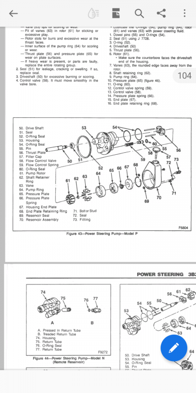
(1) This from the 1989 GMC Light Duty Truck Unit Repair Manual, pg. 3B3-2 POWER STEERING.
The GM manual states:
"There are two bore openings at the rear of the
pump housing. The larger opening contains the
cam ring, pressure plate, thrust plate, rotor and
vane assembly, and end plate. The smaller opening
contains
the pressure line union, flow control valve,
and
spring. The
flow control orifice is part of the
pressure line union. The
pressure relief valve inside
the
flow control valve limits the pump pressure."
Figure 31 (below) is from the same document and illustrates the
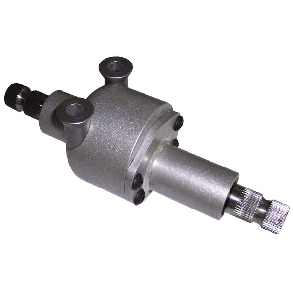
flow control valve (#21 in the figure) and the "fitting" (#23); this "fitting" is the
pressure line union mentioned in their text above. It is also known as the "union" shown as #1 in the illustration I posted prior. Even GM's documents don't use consistent terminology for this device, although none of them mis-label it as a "flow control valve", because it's not.
You must be registered for see images attach
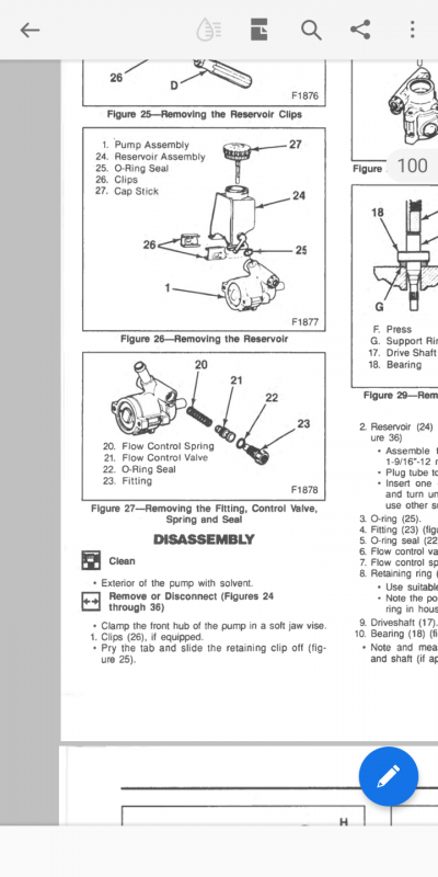
Notice how the GM manual states the "flow control
orifice" is in the
pressure line union. GM's "EVO" also resides there. Note that this same
pressure line union is illustrated in the document once reference by
@evilunclegrimace (image below, from the attached .pdf document).
You must be registered for see images attach
(2) The document titled
Steering System Principles (link below) is evidently a training document used by the Denton, TX public school system (
https://www.dentonisd.org)
The document
Steering System Principles can be found here:
The training document states:
"A
flow control valve, shown in
Figure 8-35, is used
to control fluid flow and maximum pressure. Since all
of the fluid entering and exiting the pump is not needed
at all times of the vehicle operation, the
flow control
valve will reroute fluid back to the reservoir at higher
pump rpm to reduce fluid flow and fluid temperature."
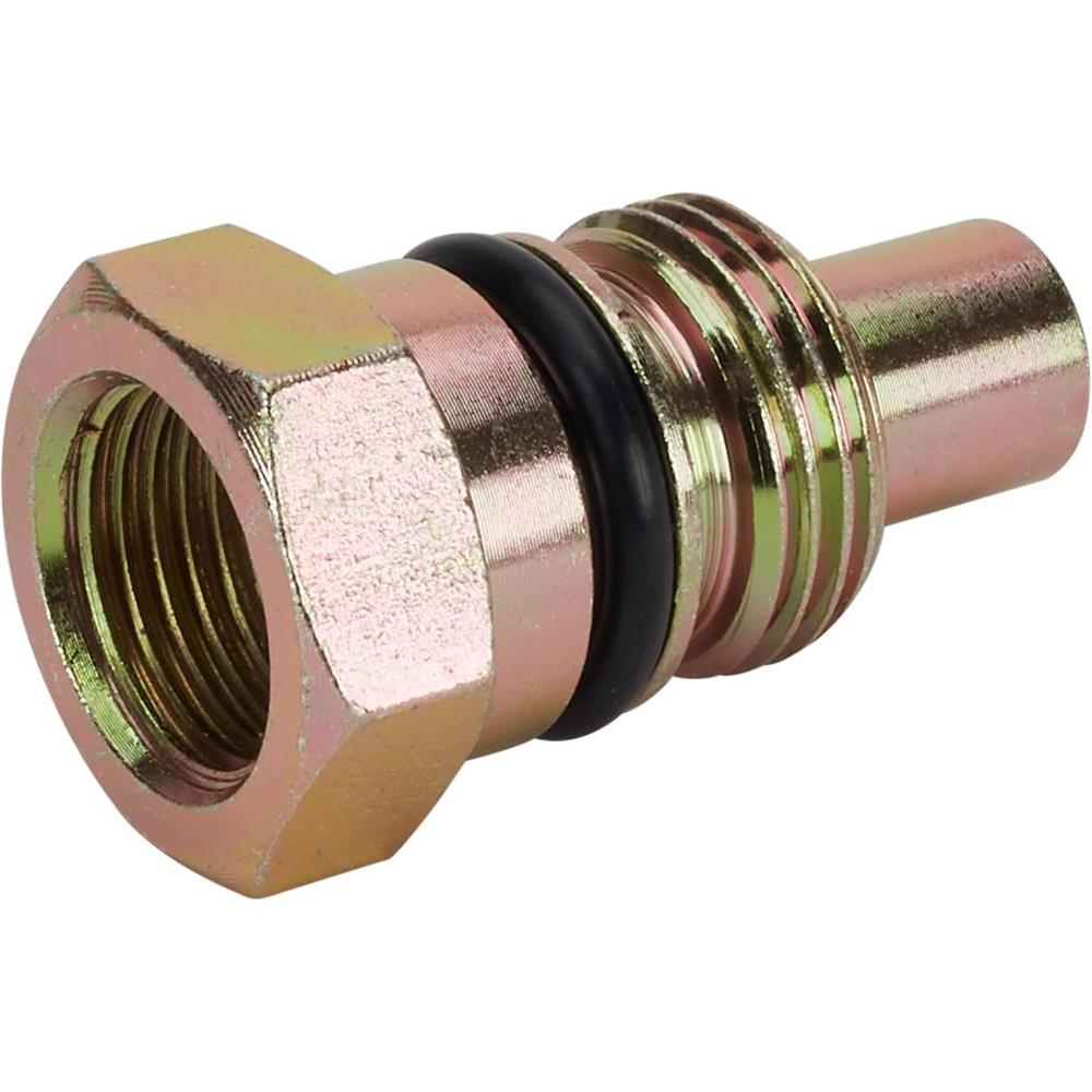
Notice their
Figure 8-35 (copied below). The "Fitting" shown there is quite obviously the same fitting I've mentioned earlier, being called a "union", "pressure line union", "pump discharge fitting" or "flow control
orifice". Others in this thread have called it a "flow control valve" and included links to sales literature as evidence, but it is not.
The
Flow control valve illustrated in
Figure 8-35 is quite obviously the same as mentioned in the illustrations I've posted prior, as item #21.
You must be registered for see images attach
(3) Finally, I happened upon a Wikipedia entry for "flow control valve", which I wasn't going to cite it as it wasn't specifically written about hydraulic power steering systems and it's "crowd-sourced" information. But its opening paragraph caught my attention. It says...
"A
flow control valve regulates the flow or pressure
of a fluid. Control valves normally
respond to signals
generated by independent devices such as
flow meters or temperature gauges."
So with respect to hydraulic power steering, the device that generates the
signal, is the "union" / "pressure line union" / "flow control orifice". The signal it generates is in the form a pressure that's related to the flow through it.
The
flow control valve then responds to the pressure signal, so as to regulate the flow.
How simple is that?
See
Flow control valve

en.wikipedia.org


")