Greetings Gmt400dually,
Welcome to the GMT400 forum. It seems that a shared appreciation for these vehicles has
brought together a lot of talent from all walks of life who are predisposed to help others
keep these machines on the road and out of the boneyard.
From my perspective,
@PlayingWithTBI just shared with you a link to the repository that
would be
invaluable for someone working to take a 32-year-old project truck and getting it
back on the road -- it's the collection of FSMs (Factory Service Manuals) that are the best
resource there is, especially for questions like yours. Let your fingers do the walking & arm
yourself with all of the '92 books for future reference.
****
The short answer to your question is
PPL (Purple). How I am sure of this (and how you can
answer other electrical wiring questions down the road) is the somewhat longer answer that follows.
****
To illustrate to you (and anyone else researching this thread for a similar problem) ...here's a
quick tutorial on how to extract real-world info from the Electrical Diagnosis & Wiring Diagrams
manual for your '92. To give you the following I downloaded the '92 Electrical manual using the
link in the previous reply. (Took <1 minute, including selecting the right file & downloading.)
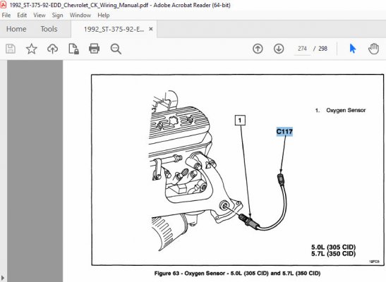
1) With the .pdf downloaded, I opened it, did an old-school "Ctrl F" [Find] ...and searched for "Oxygen Sensor".
After skipping through a few instances, I found what I was looking for in the Component Location section --
an illustration of the single, 1-wire O2 sensor used on your 5.7. In order to make sure that I could correlate
*this* O2 sensor to the proper one in the schematics, I was sure to write down
the associated connector
identified: C117.
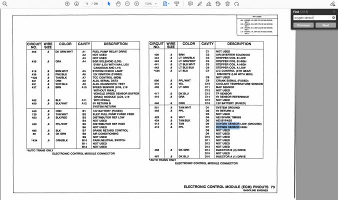
2) I then continued to search this file for all instances of 'Oxygen Sensor'
and almost immediately I found
the page in the 2nd attachment below. This is the pinout for the factory computer, and there's the rest
of the info we need in order to find the actual wires involved. Make sure and write down the
Circuit # (
412)
and check out the color listed:
'PPL'. (Purple)
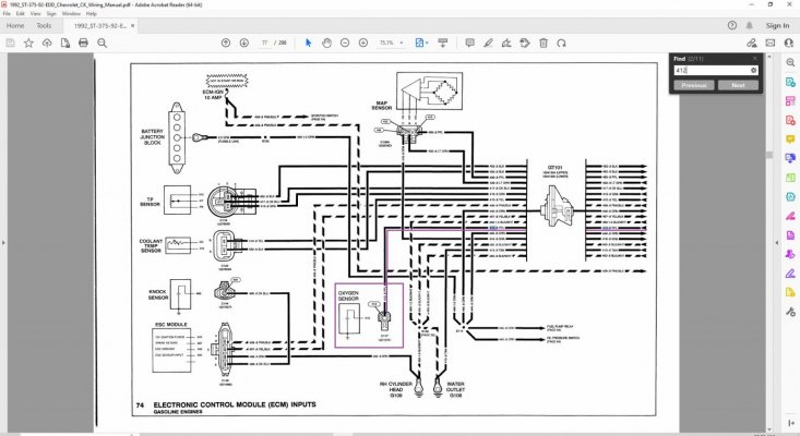
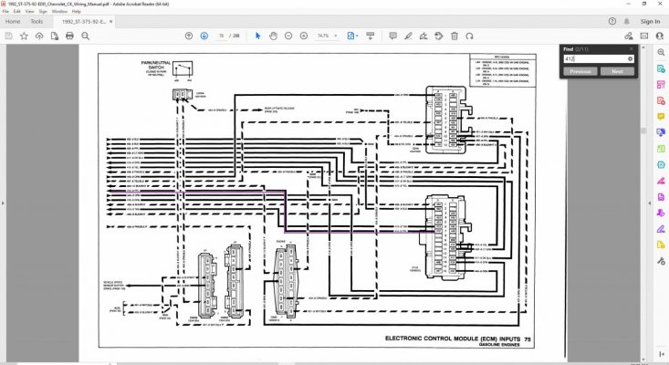
3) I then searched the document for all instances of '
412', and located attachments #3 (sensor side) and #4.
(ECM side) I used
C117 to verify that I was on the correct single-wire O2 sensor, and not on the 3-wire heated O2 sensor
documented elsewhere & used on the V6? Note: I marked up the wire of interest on both to help the reader
navigate through the wiring diagram spaghetti.
4) In the 5th & final attachment I cross-checked the first page of the .pdf file to make sure that I was really in the
correct book.
Total time spent? <10 minutes. Although I was raised on ink/paper versions, these .pdf files (on a faster laptop
with plenty of memory) are such a time-saving cheat. EDIT: These attached screen snaps are a little fuzzy when
you zoom in, but when you are referencing the actual .pdf with Adobe Acrobat you can zoom in with extreme
clarity - very useful, especially for us older dudes. :0)
****
Again, welcome to the forum, and best of luck with your project.
Cheers --