Needing help with wiring tool box lighting??

Disclaimer: Links on this page pointing to Amazon, eBay and other sites may include affiliate code. If you click them and make a purchase, we may earn a small commission.

ChevyK1500

Newbie
Joined
Aug 21, 2012
Messages
20
Reaction score
27
Location
Carroll Iowa
Okay, so heres the deal: im wiring lights into by tool box (black plastic) and I got all the wires ran and hooked up to the lights, but they are not working. im wanting to run two clearance lights on each side of the tool box that also double as turn signals, and five red lights on the rear of the box as running/brake lights. They are all LEDs. I have the four side lights wired to the far outside turn signals on each side (because it works as running light and turn signal in one line, and thats how i want the lights ran running/turns) and the brake/ running lights are hooked up to the brown wire to the lights in rear, and as far as i understand it is Yellow=turn, Green=turn, White=ground, and brown=running/brake. and for a ground i have them all wired into one ground. i was told that i can do that but was i told wrong? should i have three different grounds going in? one for left, one for right, and one for brake? or can i just leave it the way it is? i have the ground spliced into a ground going into the actual tail lights, so the ground wire is a little long.
You must be registered for see images attach

^how i have the positive wires wired.
You must be registered for see images attach

^how i have the ground wire ran under and in the tool box.

is there something little im doing wrong here that im just not seeing? or do i have to figure out an entirely different way to wire my lights in? any help would be greatly appreciated. =)
 

ChevyCowboy22

Newbie
Joined
Jun 25, 2012
Messages
13
Reaction score
0
Location
New London, MO
well your factory wires are DARK GREEN-RIGHT TURN/BRAKE, YELLOW-LEFT TURN/BRAKE, BROWN-PARKING LIGHT not sure if the ground is black or white. so knowing this i know that unless your led lights have 3 wires coming out of them then you cannot run them as running lights and turn signals. if you wire them into your turn signals then theyll light up solid everytime you hit your brake pedal. if they are 3 wire lights then double check how you have them wired if there just 2 wire lights then double check which is power and which is ground and then i would just wire then into your brown parking light wire. as far as your ground goes, having them all ran together is fine but i would just drop is down to the frame somwhere and either drill a hole and bolt it or take a bolt out and ground it there instead of having it ran all the way back to your tailights. I hope this helps.
 

Half Assed

WINNERS NEVER LIFT
Joined
Feb 16, 2012
Messages
1,216
Reaction score
41
Location
SARASOTA
What am I reading... so confused lol

Are the LEDs able to do running/brake? As in dim and bright?

For the side markers I would splice power from the front turn signals. The brake lights from the tail lights. I will draw a wiring diagram tomorrow...
 

Sumbitch

I'm Awesome
Joined
Dec 15, 2012
Messages
475
Reaction score
12
Location
USA
so knowing this i know that unless your led lights have 3 wires coming out of them then you cannot run them as running lights and turn signals.
If the desired look is that the tool box side lights flash IN SYNC with your OEM turn signals, this statement is true. A typical trailer turn/brake/running light would be your only option in this case with LEDs. Which can run you $20-40 a light, as compared to marker lights that cost $5-10.

However, if you'd be willing to spend a lil bit more cash ($10-15) and time for this, there is a way to have your tool box side lights still signal your direction of turning AND have them as marker lights. (There isn't a way to get your red lights to be running AND brakes besides buying a trailer turn/brake/running light) Keep in mind, as of right now, this plan is a theory I have yet to prove 100% correct. But I can say with 90% certainty that it should.

You wanna get two 5-prong relays/isolated switches. I'm assuming that you want your tool box lights to turn on when you turn your headlights/parking-lamps on. In which case, the two relays are all the extra materials you need (besides more wire if you think you're running low and Push-On female wire terminals to connect to the prongs on the relays).

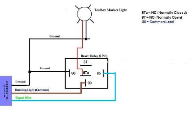
:) Here we go. I'll explain this for the driver side lights and you can repeat these actions for the passenger side (differences will be mentioned). Run your positive wires to your LED's down your frame and up into your engine bay/under the hood. Be sure to have your left and right side wires separate. Pick a nice spot to mount the relays that allows for easy access and installation. Get a hold of your front marker lamp wiring (best to just take off the marker lamp housing and pull the bulbs out). According to a 94-98 wiring diagram, there should be three wires there. One Brown (running lights), one Black (ground, leave alone), and one LIGHT BLUE (left signal light). You're better off splicing into the brown wire with TWO wires, one for the left side running light relay and one for the right. This makes it easier to wire into your relays, because you'll most likely mount the relays somewhere on the driver side of the engine bay. You then want to splice into the LIGHT BLUE wire and run that to your driver/left side relay. This here is a diagram I found and tweaked to match this here application:
109717[/ATTACH]"]
You must be registered for see images attach


You want to ground your relay to any nearby bolt that is already grounding something or makes bare metal contact with the body/frame. Splicing into OEM ground wires is just a waste of time because the point of grounding something is that you only have to run one wire (positive) to your load and then ground it nearby. Follow the diagram for your passenger side marker light wiring process, except the passenger side directional/turn signal wire is BLUE (not light blue. normal blue). That honestly should be all you need to do. Clean everything up and you should be solid. Good luck!

The outcome will be that when your OEM maker light is on, your side toolbox lights will be on. When you activate your signal, your toolbox light will flash OUT OF SYNC with your OEM turn signals. When your OEM signal light flashes ON, your toolbox marker/turn light for that side will be OFF. When your OEM signal light flashes OFF, your toolbox marker/turn light will be ON. Its different and unique. I wired a set up like this on a buddy of mine's headache rack and it looks pretty cool. It wasn't wired up the exact same way because he had incandescent lights so we were able to take a few shortcuts cause polarity doesn't matter for incandescent lights, but for LED's it does.

BTW: The reason a 5-pin relay should be used is because its simpler, and if you ever want to put lights on that are ONLY turn signals, you can plug them into pin 87 and they will flash IN SYNC with your OEM signal lights. They won't work as running lights though.

I know this post is probably super late and may no longer be useful to the original thread poster. I feel that this will help anyone else who is searching on how to wire up marker lights into running AND turn signals.
 

Attachments

  • Outofsyncturnsignalrelaydiagram_zps9d584209.jpg
    Outofsyncturnsignalrelaydiagram_zps9d584209.jpg
    35 KB · Views: 0

addiction2bass

junkyard junkie
Joined
Jun 6, 2012
Messages
967
Reaction score
16
Location
Brownsburg, IN
well first off LEDs are very picky with power... you can not wire them backwards... it could be your leds are just wired reverse. simply switch power and ground wire on the leds or pull lenses off if you can turn the leds around.
and you can wire them any way you want if you have alittle time to play around with wiring! i made a skull trailer insert i made into led lights as well into it. it lites up dim with parking lights, and full brightness with brake lights and turn signals.
i used afew resistors soldered inline till i got the right dimness i liked, then added some diodes which prevent voltage back flow.
You must be registered for see images attach


You must be registered for see images attach

You must be registered for see images attach

You must be registered for see images attach

You must be registered for see images attach

You must be registered for see images attach

video
You must be registered for see images attach


the grey wire gets power from both sides after the resistor groups to power the mouths leds. white wires go to left or right leds, 2 groups green is simply full power brightness with diode, and blue wire has 2 resistors soldered inline and diode to dim the leds down to my liking. just be sure to put a diode inline of the wiring so NO power flows back thru the other circuit! plus diodes only flow power one way SO BEFORE YOU SOLDER THEM IN make sure you got them the right way! otherwise they will not let power thru and your lights wont work ;)
just go to radio shack and buy a small bag of diodes and assorted pack of resistors and just experiment with the resistors inline to get your desired amount of dimness, if not dark enough just keep adding resistors till its how you want it!
i am in no way a resistor person and couldnt even tell you what ohms resistors i used... i just keep adding different ones till its how i like it! then just solder away, snip off extra and heat shrink or tape up all the parts so they wont short out on the other wire or anything else. this is my second set i made. first skull i made only lasted about a year because i didnt seal over the leds and road salt got into the leds and basically the 2 metal prongs powering the leds rusted out so i had to make anew one and this time i sealed the leds all over front and back with clear epoxy so they should last along time now! ;)
i have mine wired into a trailer harness wiring. with a plug inside my hitch so i can simply unplug it to slide in a hitch to tow. i like it! not your normal ugly skull with a single light! its my favorite skull hitch cover :) i just added my own led lights!

video with it on my truck at night.
You must be registered for see images attach
 

Sumbitch

I'm Awesome
Joined
Dec 15, 2012
Messages
475
Reaction score
12
Location
USA
well first off LEDs are very picky with power... you can not wire them backwards... it could be your leds are just wired reverse. simply switch power and ground wire on the leds or pull lenses off if you can turn the leds around.
and you can wire them any way you want if you have alittle time to play around with wiring! i made a skull trailer insert i made into led lights as well into it. it lites up dim with parking lights, and full brightness with brake lights and turn signals.
i used afew resistors soldered inline till i got the right dimness i liked, then added some diodes which prevent voltage back flow.
You must be registered for see images attach

Nifty work there A2B! I got a plastic Ruger emblem hitch cover that I want to put smoked red component LED's in. Just as running and brake lights, nothing very fancy. Might have to refer to this thread whenever I feel like getting around to that. I'm pretty sure the OP is using marker lights that contain LED's, and isn't attempting to mount component LED's to his tool box. Gosh would that take FOREVER. :D
 

addiction2bass

junkyard junkie
Joined
Jun 6, 2012
Messages
967
Reaction score
16
Location
Brownsburg, IN
it still works for any led light resistor wise and diode wise. i used mine for groups of 3 prewired leds but the same way will work for any led setup! just try different resistors until they are dim to your liking for running lights. hell you could even do top cab lights if you change out the bulbs to led lights in the sockets. dont think ive seen that mod done yet. ;) running lights also wired into turn signals.
just get creative thinking and try it out! i got a bag of wires with clamps on each end which i use for quick testing all the time. they work great cause you dont have to twist any wires together or resistors, just clamp onto some and its great for experimenting!
 

Sumbitch

I'm Awesome
Joined
Dec 15, 2012
Messages
475
Reaction score
12
Location
USA
it still works for any led light resistor wise and diode wise. i used mine for groups of 3 prewired leds but the same way will work for any led setup! just try different resistors until they are dim to your liking for running lights. running lights also wired into turn signals.

Huh. I guess I was naive enough to believe that once LED's are wired up, you can't do anything else to em besides plug em in. So, for example (just to make sure my understanding of what you said is correct), I can connect running lights and turn signals into the positive wire on the pre-wired LED (single positive wire) light. I put a few resisters between the running light wire and the postive LED wire, and a diode after that so as to keep it from backfeeding. Then connect a turn signal wire to the LED light positive wire and a diode on that as well. My runners will be dim (to my liking as you say) and whenever the turn signal wire becomes hot, the pre-wired LED light should brighten right up? Is this correct? If so, I feel like I have unlocked a whole new world in making pickups look like big rigs.
 

addiction2bass

junkyard junkie
Joined
Jun 6, 2012
Messages
967
Reaction score
16
Location
Brownsburg, IN
o no you can still do some tricks to them ;)
JUST BE SURE TO USE A DIODE ON BOTH INPUTS!!!!! you do not want voltage to go back thru stock wiring! otherwise ya got some lighting problems with brake lights lighting up with the running lights or vise versa.
you can do quite a bit if you know somebody with some computer skills as well! building Sequential for chaser lights.
http://www.youtube.com/watch?v=S5HXvHlgBqU

i wish i could make those sequential lights! hell id love to have them for my 66impala with some led lights in my taillamps!

but either way you can do your testing with a single light or for a group of lights. but i would suggest you test them all together how your going to wire them. it would be easist to wire them with 2groups one for left and one for right and then just wire the led lights in parallel off that positive wire resistor group. but either way id test them all out together on the bench so you can see exactly how they light up!
and to be able to test 12volt electronics most people can simply dig thru old electronics and find a power plug that says 12V output. the more amps it has the better but small ones will work alright for minor tests of most electronics like lights or radios. one i use is 1amp output at 12Volts. works pretty good on lights and testing radios with one speaker i can usually turn the radio up to atleast half way before the radio cuts out from not enough voltage.
i always look thru old electronics to see if those power transformers are usable or not. my latest one i just got came from a cable box and puts out like 3amps. just cut the connector end off and strip the wires back and use a prewired led to test which wire is positive and which is negative and then just mark the wires for future reference. works great for testing and since its recycled its free ;)
 

Sumbitch

I'm Awesome
Joined
Dec 15, 2012
Messages
475
Reaction score
12
Location
USA
o no you can still do some tricks to them ;)
and to be able to test 12volt electronics most people can simply dig thru old electronics and find a power plug that says 12V output. the more amps it has the better but small ones will work alright for minor tests of most electronics like lights or radios. one i use is 1amp output at 12Volts. works pretty good on lights and testing radios with one speaker i can usually turn the radio up to atleast half way before the radio cuts out from not enough voltage.
i always look thru old electronics to see if those power transformers are usable or not. my latest one i just got came from a cable box and puts out like 3amps. just cut the connector end off and strip the wires back and use a prewired led to test which wire is positive and which is negative and then just mark the wires for future reference. works great for testing and since its recycled its free ;)

couldn't a guy just hook em up to a 12v jumper box? I got one for Christmas last year (never even asked for one. I'm sure every 16 year old would rather have that than $50 cash) and have only seen to its proper and purposeful use once or twice. And not even for my truck.

Its my understanding that component LEDs don't NEED resistors when being ran on 12v cause its too low of voltage to cause any harm. Correct? lol. I feel so foolish having come into this thread headstrong and now I'm asking quite a few questions.

EDIT: No longer is it my understanding that compnent LED's don't NEED resistors because I just hooked em up to a 12v jumper box (which I've used to test numerous amounts of pre-wired LED lights) and I broke two LED's, thinking one was just a fluke. Guess I'll just go back to radio shack and pick up some more LED's and some resistors.

Right now my current plan (current as in I'm actually putting a plan into action. I like to plan. I like to execute plans about a quarter as much as I like to plan) is making interior "dome" lights outta 5mm White LEDs and 12 gauge shotgun hulls (just the brass). Removing the primer and drilling the primer picket out to fit the light into the pocket and epoxy them in. I have a thread with more details on it and what it should look like. My dad shot trap for 20 years and reloaded shells for, well about 19.5 years. So I got plenty of free shells and equip to work with the shells and LED's + wiring + accessories are fairly cheap. And a great way to enhance a vehicle's appeal!
(i love LEDS! last night, wired two white LED strips my buddy got from orielly's for like $10 in his truck and put one strip on the windshield above the rearview and one on the top of the back window. BRIGHT AS HELL! A guy could find a lost contact in his dirty truck within 15 seconds with those lights on.)
 
Last edited:
Top