Horn problems

Disclaimer: Links on this page pointing to Amazon, eBay and other sites may include affiliate code. If you click them and make a purchase, we may earn a small commission.

densobro

Newbie
Joined
Apr 30, 2022
Messages
41
Reaction score
42
Location
Cedartown, GA
Ah I found a female end plug that with a green wire that doesn’t fit in the the original plug, may be because of the wrong harnesses installed years ago (I heard they rebuilt the truck using parts from a different truck).
When I rig the plug to work with the horn plug nothing happens until I use a jumper wire where the relay should be. But nothing happens when I try to honk the horn on the steering wheel. Now I believe the switch in the steering wheel is bad because it’s not completing the circuit for the horn. I will remove the air bag and horn switch tomorrow when I get time because it’s starting to get dark out and the wife is mad I’ve been out here all day. Ill keep you updated, thanks
You must be registered for see images attach
for the help!
 

densobro

Newbie
Joined
Apr 30, 2022
Messages
41
Reaction score
42
Location
Cedartown, GA
There should be a wiring harness right below the cruise control it has red wires that coming out and into the fuse box then there’s two green wires that feed out. There should be a connector there.
You must be registered for see images attach
Also do those two green wires come from the single positive red wire that’s protected to the right or the bigger protected bundle of wires to the left? Kinda hard to make out the location the green wires are coming from
 

97Kharon

OBS Enthusiast
Joined
Jul 8, 2023
Messages
73
Reaction score
83
Location
San Antonio
You must be registered for see images attach
Also do those two green wires come from the single positive red wire that’s protected to the right or the bigger protected bundle of wires to the left? Kinda hard to make out the location the green wires are coming from
Hello again I just saw your reply, the wires come from the bigger bundle of wires which I assume come from the inside the cab (Behind and under the dash). I’ll look at a few diagrams to better answer your question.
 

Road Trip

Supporting Member
Supporting Member
Joined
Jul 8, 2023
Messages
1,119
Reaction score
3,194
Location
Syracuse, NY
I would really appreciate that. I’ve been almost to the point of going to my neighbors house (who I’ve never met, but has the same year truck) and asking them if I could look into their engine bay to see where their plug goes haha. Probably not the best way to introduce myself.
And I followed the steps in the trouble shoot guide and it kept leading me to the same question that I couldn’t answer, I think it was #7

Greetings densobro,

I've got a '99 C2500 where the wiring looks to be factory original. I've read your thread with interest,
and I decided to try to help by physically verifying the "Horns Schematics" in the Service Manual with
how my circuit is actually physically wired. The good news is that my '99 matched the wiring schematic
*exactly*.

Disclaimer: Now given that your '96 (with unknown previous repairs) won't match my '99 exactly, at
least you will be able to see what it looks like when the truck is wired per the schematic.

****

OK, I took @97Kharon 's schematic & marked it up so that when we look at the actual wiring underneath
the Underhood Fuse Block it will make more sense:

Color coded overlay on factory Horn Schematic
You must be registered for see images attach


Healthy Circuit Behavior:

1) Working backwards from the horn assemblies, +12 volts is sent only during actual horn operation
on the green wire between the relay output and the horn connectors. The (verified) physical path
is from the Underhood Fuse Block to C100, (main connector on firewall to IP**) then to C102,
(IP Harness Inline to Forward Lamp Harness) which then runs from beside the engine's black box
all the way over to the horns in front of the single battery on the passenger side. NOTE: In a subsequent
post I'll share the physical path photos for this green wire so that you can compare what I've got to
what you have.

2) The path between the steering wheel horn switch and the control input to the relay is colored black
to denote a ground circuit, but for troubleshooting purposes I'd like to point out an important fact.
If you look closely at the circuit, as long as there is a charged battery in the truck & the Horn Fuse is
not blown, if you were to take a voltmeter to any part of the wire feeding the horn switch you will see
+12 volts parked on the wire. Of course, there is zero current flow until the driver smashes the horn
button, applying the ground, current flows, and the relay is energized by this flowing current.

I share the above because you can use this knowledge to your advantage while troubleshooting. As
you follow the wiring from C100 to the "Convenience Center", you can check pin 'F' at C(onnector)210,
and if the +12 volts is there, then on to C266 (IP Harness Inline to Steering Column Harness) pin A11.
If the power is now missing, we know where to look. Otherwise, it's up the steering column & to the
horn switch & the associated ground.

NOTE: Most people prefer to check for voltage, while the old, grizzled shade tree mechanics would apply
a ground to the points listed in the previous paragraph. Ground to pin F = horn blow! Ground to pin A11 = horn blow!
Now they would have it narrowed down to either an open in the steering column or the horn switch/ground itself.

CAUTION: Using a voltmeter is being a lot more cautious than applying a ground while troubleshooting.
Why? Because if you NEVER make a mistake, applying a ground is a valid troubleshooting method on this
side side of the horn circuit. On the other hand, what IF you miscount & apply ground to the wrong pin
in the connector? Best case, you will have to find the fuse on some unknown circuit that you just blew.
Worst case, you may very well just smoked something unrelated yet spendy!

Conversely, voltmeters make their measurement with very low amounts of current, and therefore are very gentle
(think butterfly wings) on auto circuits = very forgiving not if, but when you hit the wrong pin. :0)

****

Apologies for dragging you through the circuit, but now I can better show you what I found on the underside
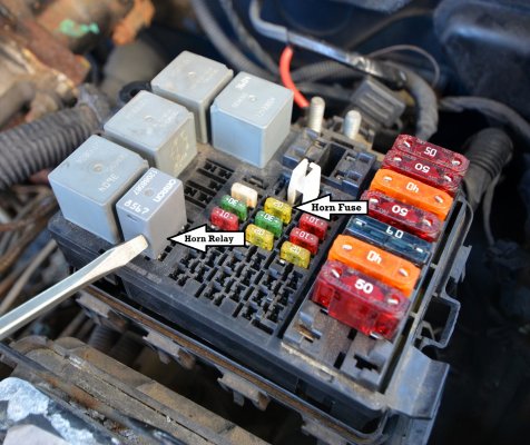
of the Underhood Fuse Block on my truck:

Check this out - Orange, Green, & Black wires just like the "Horns Schematics" promised!
You must be registered for see images attach

NOTE: A better description for the black wire might be: "Ground from steering wheel horn switch" (current to ground energizing relay when switch depressed/closed.)

One last thing. I did the 'trust but verify' thing by first removing the Horn Relay & verifying that the horn no workie. Reinstalled relay &
removed the 20A horn fuse -- also no workie! Given this, I now have 100% confidence in both what the schematic and the photo above is showing.

****

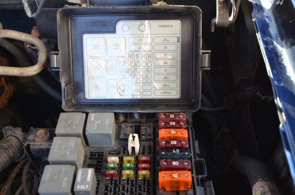
OK, for those reading along but you haven't needed to find the horn fuse and/or relay, I've attached a couple of photos to give all this
a proper context. The Underhood Fuse Block is in the right rear corner of the engine bay closest to the driver as seen from the front. (See attached.)

In my next post I'll document the physical path that the green horn wire takes from relay to the horn assemblies for your viewing pleasure.

**IP = Instrument Panel
 

Attachments

  • horn relay installed (arrows sml).jpg
    horn relay installed (arrows sml).jpg
    546.1 KB · Views: 27
  • underhood fuse block & legend(sml).jpg
    underhood fuse block & legend(sml).jpg
    218.7 KB · Views: 28
Last edited:

Road Trip

Supporting Member
Supporting Member
Joined
Jul 8, 2023
Messages
1,119
Reaction score
3,194
Location
Syracuse, NY
Physical path of green wire feeding horns on factory stock '99 C2500:

Horn Relay pulled from socket & laid on it's side, showing electrical schematic printed on it.
You must be registered for see images attach

According to the schematic, the green wire is connected to pin 'D1' of the Underhood Fuse Block. (Lower right hand pin as seen here - see previous post for the green
horn wire physical correlation.)

Jumpering +12 volts to this pin = horn blow!

C100 is obscured & couldn't photograph. It's on the firewall directly behind the fuse block. But the connector after C100 is C102, as shown here.

You must be registered for see images attach

Note: This connector is situated between the fuse block and driver's side front fender. If you look closely, you will see the green wire at Pin G. (C102, p. 8-463 in Vol. 4, '99 C/K)


This is the "Forward Lamps Harness" as it runs past the engine's Black Box.

You must be registered for see images attach

Note: I've opened the convoluted tubing in order to verify that the green horn wire of interest is actually running within. Yes.


Forward lamps harness heading down in the vicinity of the Driver's side headlight.
You must be registered for see images attach


Green wire at horn connector. Horn is a bit rusty but still full-throaty! (Disconnected in order to make green wire visible.)
You must be registered for see images attach

NOTE: On my truck, this horn is mounted directly in front of the single passenger-side battery.

****

Given what you have shown in your photos vs. the wiring in my truck, this is the suggested way forward:

1) Your troubleshooting where you applied +12V to the connector was good! All you need to do is find the
green wire under your existing Horn Relay & splice your proven-good wire to that.

2) Now to get the steering wheel horn switch to energize the relay. (You said you got it to click already?)

Given your troubleshooting progress so far, I am convinced that you will get the horn operational soon!
And hopefully these photos above will give you an idea of what the factory wiring looks like between the
Underhood Fuse Block & the horns.

Happy Hunting...and let us know what you discover!

Cheers --
 
Last edited:

densobro

Newbie
Joined
Apr 30, 2022
Messages
41
Reaction score
42
Location
Cedartown, GA
Physical path of green wire feeding horns on factory stock '99 C2500:

Horn Relay pulled from socket & laid on it's side, showing electrical schematic printed on it.
You must be registered for see images attach

According to the Underhood Fuse Block, the green wire is connected to pin 'D1'. (Lower right hand pin as seen here - see previous post for green wire physical correlation.)
Jumpering +12 volts to this pin = horn blow!

C100 is obscured & couldn't photograph. It's on the firewall directly behind the fuse block. But the connector after C100 is C102, as shown here.

You must be registered for see images attach

Note: This connector is situated between the fuse block and driver's side front fender. If you look closely, you will see the green wire at Pin G. (C102, p. 8-463 in Vol. 4, '99 C/K)


This is the "Forward Lamps Harness" as it runs past the engine's Black Box.

You must be registered for see images attach

Note: I've opened the convoluted tubing in order to verify that the green horn wire of interest is actually running within. Yes.


Forward lamps harness heading down in the vicinity of the Driver's side headlight.
You must be registered for see images attach


Green wire at horn connector. Horn is a bit rusty but still full-throaty! (Disconnected in order to make green wire visible.)
You must be registered for see images attach

NOTE: On my truck, this horn is mounted directly in front of the single passenger-side battery.

****

Given what you have shown in your photos vs. the wiring in my truck, this is the suggested way forward:

1) Your troubleshooting where you applied +12V to the connector was good! All you need to do is find the
green wire under your existing Horn Relay & splice your proven-good wire to that.

2) Now to get the steering wheel horn switch to energize the relay. (You said you got it to click already?)

Given your troubleshooting progress so far, I am convinced that you will get the horn operational soon!
And hopefully these photos above will give you an idea of what the factory wiring looks like between the
Underhood Fuse Block & the horns.

Happy Hunting...and let us know what you discover!

Cheers --
I couldn’t thank you enough for the in-depth help, I will for sure check for all of this Monday when I’m off work and let you all know what I come up with, thanks again!
 

Road Trip

Supporting Member
Supporting Member
Joined
Jul 8, 2023
Messages
1,119
Reaction score
3,194
Location
Syracuse, NY
It's always a pleasure to help someone who's working a problem as diligently as
you are. I know when I'm troubleshooting something that hasn't worked since it
was last repaired/modified by some unknown mechanic, all I want to know is
what was it originally like when it rolled off the assembly line?

Given the above it seemed only right to take a few pics & share the factory
layout w/you. Good luck with tomorrow's troubleshooting session, and be
sure to share what you discover...
 
Top