Hey Guys I Need Help Quick

Disclaimer: Links on this page pointing to Amazon, eBay and other sites may include affiliate code. If you click them and make a purchase, we may earn a small commission.

Road Trip

Supporting Member
Supporting Member
Joined
Jul 8, 2023
Messages
1,117
Reaction score
3,184
Location
Syracuse, NY
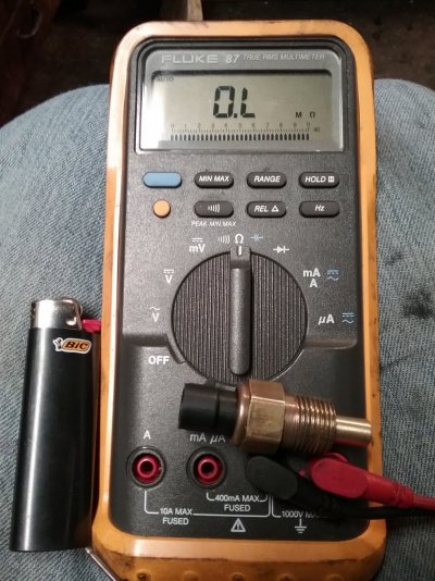
Any ideas why the truck ran so good for a bit with knock sensor disconnecEd then ran like crap again after 10 minutes of it disconnected?

Nick88,

Upon further digging I think that I may have been giving the 'TBI-era' ECM too much credit? As in,
thinking that the older/slower technology TBI computer is running the more complex '96+ Vortec-era'
KS check algorithms?

To be more accurate, let me quote a TBI-era FSM on the KS check:


You must be registered for see images attach


So many people look down upon on the inherent simplicity of the TBI design. I happen to subscribe to the notion that
simplicity is the sign of good engineering.

Anyway, to improve the signal/noise ratio, instead of just having the Knock Sensor feedback signal rise up from 0 volts, the engineers
instead have set up a voltage divider network, where the +5v reference signal is sent from the computer to the Knock Sensor.
And thanks to an internal 3900 (3.9K) ohm resistor, this results in a steady mid-range value of 2.5V DC.

And then the actual Knock Sensor feedback signal (similar to a microphone output) AC dances on top of the steady 2.5V DC voltage.

By doing the above, this also allows the engineers to be able to detect an Open Circuit (at/near +5v reference) or a Short to Ground.
(at/near 0 volts) Re-reading the above, it looks like >4.3v or <.64v is supposed to set/store the DTC 43 code. (!)

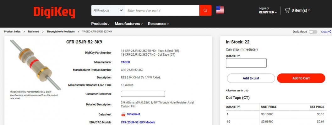
Check this out. For the affordable price of a single 3.9K ohm resistor (see attached) we could temporarily substitute this resistor
in place of the Knock Sensor, which will prevent the ECM from kicking the DTC 43 code and going into the Limp Home ignition timing
mode. So, if by faking the TBI-era ECM to believe that the Knock Sensor is in circuit, and it proceeds to drive right, then we have
identified the Knock Sensor as the root cause of the driveability issue.

I know that I sound overcautious about all this, but I hate the thought of spending other people's money with via a remote diagnosis
parts cannon.

So, in increasing order of confidence, here's the path from here.

* 1) Replacing the Knock Sensor based on the 10 minutes of improved running right after previous disconnection. (promising, but a bit iffy)
* 2) Clearing the ECM memory, getting the bad driveability to reoccur, disconnect the KS a second time, and again this temporarily
fixes the problem. (I'd take this as confirmation, and would personally change the Knock Sensor.)
* 3) Temporarily substituting a 3.9K ohm resistor for the KS, clear ECM memory, and then truck drives nicely for extended periods of time?
I would recommend in public that you change the Knock Sensor.
* 4) Get a Schurkey level dude with a period-correct pro level OBD1 scan tool involved. Take them for a ride-along while monitoring the data.
Do whatever they recommend. (Failsafe approach. :0)

****

Don't know how much electronics background you have. If this isn't in your comfort zone, do you have a zany
buddy who's a sparky type? If so, show him the circuit in the FSM and the resistor listing. If he's good, he may
have one of these resistors sitting in his stash. It's not as Macguyerish as it sounds. It's a simple fake for a simple ECM. :0)

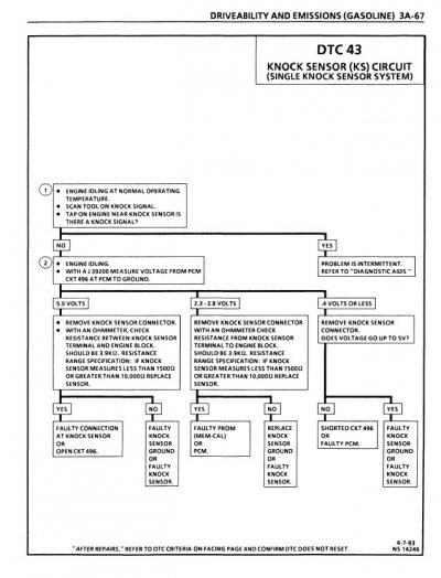
EDIT: I've added the associated troubleshooting tree as an attachment for your sparky type to review. Of
course live data is the best of all, but this gives you an idea of how the General wanted the techs to verify
proper KS circuit operation.

****

One last thing. I'm seeing others recommending timing, vacuum, and compression checks. I'm assuming that
from your previous comments that all this has already been adequately covered. And I know that I won't start
messing around at this level unless I'm at the point where I know that the engine would be running just fine
with a conventional carb & mechanical distributor involved...so I'm just dealing with a 'ECM management' issue?

Apologies for any convolution here, this is a bit hard to explain via the written word from a remote location.

At the very least, run that KS disconnect test a 2nd time (per the instructions above) ...and let's see what you got.

For what it's worth, if everything else is accounted for, then it's starting to smell like a bad KS to me.

EDIT: The only question mark remaining is why no stored codes/steady SES light when the KS was
disconnected? If we decide to replace the KS and the problem remains, then there's the outside chance
that the ECM is starting to flake out due to old age? But given the cost associated with a rebuilt ECM,
I for one will try everything else first and only replace the ECM as a last resort. (Just trying to cover all
the bases for completeness. The 10 minutes of good running gives me hope that you are within a KS
replacement of restoring good behavior in the engine bay.)

Best of luck. Looking forward to seeing what you discover.
 

Attachments

  • 3.9K resistor to temp sub for KS --CFR-25JR-52-3K9 YAGEO  Resistors  DigiKey — Mozilla Firefox...jpg
    3.9K resistor to temp sub for KS --CFR-25JR-52-3K9 YAGEO Resistors DigiKey — Mozilla Firefox...jpg
    118.6 KB · Views: 2
  • DTC 43 TBI-era troubleshooting tree - 1994_NATP-9442_DRIVEABILITY_EMISSIONS_ELECTRICAL_DIAGNOS...jpg
    DTC 43 TBI-era troubleshooting tree - 1994_NATP-9442_DRIVEABILITY_EMISSIONS_ELECTRICAL_DIAGNOS...jpg
    96.7 KB · Views: 0
Last edited:

Jroctizzle

Newbie
Joined
Apr 10, 2022
Messages
39
Reaction score
72
Location
Edmonton, Canada
That's not quite true, the Minimum Idle Stop screw should always hold the butterflies open (unless someone messed with it). When you set Min Idle, you close the IAC all the way, then adjust it.
That makes sense, the one I got from the wreckers was missing the screw cap so when I adjusted my min idle after resetting my iac (tracking down the vacuum leak) it wouldn’t start with the (iac) port plugged.
 

Road Trip

Supporting Member
Supporting Member
Joined
Jul 8, 2023
Messages
1,117
Reaction score
3,184
Location
Syracuse, NY
So do you think it’s the knock sensor being bad, so when I popped it off it was how it should be then the computer got a little freaked out with no signal causing it to drop timing.

Your query came in while I was writing reply #61 above. The short answer is Yes. You are picking up what I'm putting down correctly. :0)


Would that mean a new knock sensor might fix my issue maybe??? The check engine light didn’t come on with it disconnected, but I do know it is functional because it is on with the key on but engine off, but it shuts immediately when engine turns over

This is a good status report. It's a low hurdle, but digging any deeper into a ECM that can't
figure out how to work the SES light at a very basic level usually leads to lots of needless troubleshooting
frustration.

Since I don't have the code (listings) or the printset for your ECM, I can't say for sure if your ECM is
working 'as programmed' or it's having a senior moment. And as for the resistor substitution, if I had
firsthand experience doing this and it worked to figure out a bad KS then I would sound much more
confident in this test strategy. But since I'm driving a '99 C2500 I can't try this on my own vehicle, or
I would. But reading the FSM this is how I would proceed. (I mean it might be easier to just throw in
a new sensor and see what happens, but we've recently worked through a similar issue where not 1 but
2 brand new sensors (from a name brand) didn't work, and it took a 'NOS' sensor to finally get a TBI-era
GMT400 vehicle to straighten up and fly right?)

Anyway, after verifying that all the mechanical variables are 100%, then let's retest and then follow the
data where it leads us. I think that you are narrowing it down to the final fix.

FWIW --
 
Last edited:

Nick88

OBS Enthusiast
Joined
Mar 15, 2024
Messages
74
Reaction score
31
Location
New York
very interesting, i decided to just get a new knock sensor. I read other posts about it and how it plugs into some sort of coolant drain or something so i expected to get wet, instead there is a black tar like substance on the end of the knock sensor and definitely no coolant?????
 

Nick88

OBS Enthusiast
Joined
Mar 15, 2024
Messages
74
Reaction score
31
Location
New York
well cleared out the sensor hole and it started pissing good. new sensor still down on power so now im gonna get a new connector for it too since the old one you can wiggle a ton on the connector, reset iac and it idled super smooth, brought it around the block and you could have used the truck as a paint shaker when I let it idle again. put in the factory iac and it seemed to fix that much, praying the connector fixes the low power or I'm stuck in another dead end
 

Nick88

OBS Enthusiast
Joined
Mar 15, 2024
Messages
74
Reaction score
31
Location
New York
Old iac fixed the idle, not perfect but wayyy lower and doesnt shake a whole bunch, still dealing with the sluggish issue, new knock sensor and connector really helped for like 30 minutes of driving but now its a slug again, dont know what else to check at this rate.
 

Nick88

OBS Enthusiast
Joined
Mar 15, 2024
Messages
74
Reaction score
31
Location
New York
well im at a loss, still having issues so far ive replaced all ignition parts, all fuel parts, cts and connector, tps Connector and verified tps, iac connector, o2 sensor, knock sensor and connector, map sensor connector and verified with another map, new egr, new pcv valve, rebuilt tbi, new manifold grounds, everything. gonna check fuel pressure again tomorrow maybe new faulty pump (its a delphi though) or maybe slight tear while installing regulator diaphragm, any ideas? maybe its a transmission issue? i doubt it though, dont feel any slip
 

thinger2

I'm Awesome
Joined
Jul 6, 2019
Messages
1,605
Reaction score
4,058
Location
Tacoma
I replaced the ECM temp sensor, AcDelco replacement, ohms are spot on and brand new connector. The problem I should have mentioned starts after it warms up, it actually runs better before closed loop, it has a new Bosch o2 sensor with only like 4k miles on the sensor
How did you test the new ecm temp sensor?
There is a chart for resistance through temperature range.
I replaced mine years ago just because and the new one was junk.
The first thing I noticed was that the plastic part would rotate freely and had slop when i pushed it or pulled on it.
You can somewhat test a cts with a meter.
Pull the cts.
clean the probe end.
With it at room temp, measure resistance between the two pins.
write that number down.
Heat the probe end of the cts with a lighter.
Dont let the flame touch it, you dont want to cook it or blacken it.
just heat it up for a minute or two just enough to change its temperature.
Measure the resistance.
It should have lower resistance when it gets hot.
Put the cts back on the bench and let it cool all the way back down to room temp.
Check resistance and compare it too your first room temp reading.
It should be pretty close.
Get some ice cubes and put them in about a half inch of cold tap water and when that water gets really cold stick the probe end of the cts into the water.
just the probe end of it,
dont chuck the whole thing underwater.
Leave in the ice water for 15 minutes or so.
Measure the resistance.
It should have higher resistance when it is cold.
Let it get back to room temp for an hour or so.
Measure the resistance.
It should be back to pretty much the same as your first reading.
This test will not tell you if your cts is operating within the range that it should.
Though I have never seen one pass this test and still be bad.
But it will tell you if it has completely failed.
There are charts for this range but I think it is much more about measuring that base line resistance against the heated resistance then back to the baseline resistance
And then going from baseline resistance to really cold and back to baseline room temp.
And that resistance should be pretty noticeable
I just pulled my spare out of the glovebox and it is at about 3 ohms at 68 degrees.
Heated the probe end with my lighter for about 30 seconds and it is at 2.4 ohms.
Dipped it my ice cold beer for awile and it is at 3.8 ohms
This is my factory 30 year old CTS.
I know that the lighter and ice cube test is not really solid enough evidence of proof of function.
Which is why I used this post to sandbag all of you doubters.
I stuck it in the freezer and pulled it out and had 8 ohms then let it warm up to room temp and got 3 ohms and then stuck it in hot water for 1.18 ohms.
And then did it again.
three times.
My lighter ice cube test is just the simple easy thing that anyone can do to see if it is actually doing anything or if it is junk.
If it passes these tests that does not make it automatically good.
It may still function in a way that is is out of the parameters that the ecm can compensate for especially if there are other contributing issues
But if it fails any of these tests it is bad.


If that makes any sense to you all.
 

Attachments

  • 17108120112871086360567.jpg
    17108120112871086360567.jpg
    355.7 KB · Views: 3

Nick88

OBS Enthusiast
Joined
Mar 15, 2024
Messages
74
Reaction score
31
Location
New York
How did you test the new ecm temp sensor?
There is a chart for resistance through temperature range.
I replaced mine years ago just because and the new one was junk.
The first thing I noticed was that the plastic part would rotate freely and had slop when i pushed it or pulled on it.
You can somewhat test a cts with a meter.
Pull the cts.
clean the probe end.
With it at room temp, measure resistance between the two pins.
write that number down.
Heat the probe end of the cts with a lighter.
Dont let the flame touch it, you dont want to cook it or blacken it.
just heat it up for a minute or two just enough to change its temperature.
Measure the resistance.
It should have lower resistance when it gets hot.
Put the cts back on the bench and let it cool all the way back down to room temp.
Check resistance and compare it too your first room temp reading.
It should be pretty close.
Get some ice cubes and put them in about a half inch of cold tap water and when that water gets really cold stick the probe end of the cts into the water.
just the probe end of it,
dont chuck the whole thing underwater.
Leave in the ice water for 15 minutes or so.
Measure the resistance.
It should have higher resistance when it is cold.
Let it get back to room temp for an hour or so.
Measure the resistance.
It should be back to pretty much the same as your first reading.
This test will not tell you if your cts is operating within the range that it should.
Though I have never seen one pass this test and still be bad.
But it will tell you if it has completely failed.
There are charts for this range but I think it is much more about measuring that base line resistance against the heated resistance then back to the baseline resistance
And then going from baseline resistance to really cold and back to baseline room temp.
And that resistance should be pretty noticeable
I just pulled my spare out of the glovebox and it is at about 3 ohms at 68 degrees.
Heated the probe end with my lighter for about 30 seconds and it is at 2.4 ohms.
Dipped it my ice cold beer for awile and it is at 3.8 ohms
This is my factory 30 year old CTS.
I know that the lighter and ice cube test is not really solid enough evidence of proof of function.
Which is why I used this post to sandbag all of you doubters.
I stuck it in the freezer and pulled it out and had 8 ohms then let it warm up to room temp and got 3 ohms and then stuck it in hot water for 1.18 ohms.
And then did it again.
three times.
My lighter ice cube test is just the simple easy thing that anyone can do to see if it is actually doing anything or if it is junk.
If it passes these tests that does not make it automatically good.
It may still function in a way that is is out of the parameters that the ecm can compensate for especially if there are other contributing issues
But if it fails any of these tests it is bad.


If that makes any sense to you all.
tested the cts, i have two AcDelco ones that are new, i used multimeter to read ohms at op temp. after sitting for a while etc. and it was all in spec, just to be sure i replaced it with another new ac delco one that i confirmed worked with multimeter and its the same difference
 

Nick88

OBS Enthusiast
Joined
Mar 15, 2024
Messages
74
Reaction score
31
Location
New York
Im gonna try fuel pressure again, when i was toying around with regulator when i had loss of power (before i figured out it was the cheap advanced auto carcrap cts) one of the screw holes on the regulator diaphragm ripped a tiny by when i was installing but i figured it was fine since i tightened the cup tight and it ran fine for a while after, but who knows
 
Top