NBS/Astro knuckle brake upgrade.

Disclaimer: Links on this page pointing to Amazon, eBay and other sites may include affiliate code. If you click them and make a purchase, we may earn a small commission.

ccreddell

I'm Awesome
Joined
Aug 6, 2010
Messages
1,253
Reaction score
200
Location
Medford, OR.
Have a question on the upper B/J. Could you do what the lifted 4X4 guys do and mount the upper B/J under the upper arm to space it down a bit for better geometry? I'm also assuming this doesnt take the place of a lowered spindle, so something like the DJM lowered arms would be required to obtain a lowered stance?
 

Shwa Kid

Newbie
Joined
Jun 9, 2021
Messages
29
Reaction score
47
Location
Canada
Have a question on the upper B/J. ...

Putting the upper ball joint below the control arm doesn't change the suspension geometry. The height of the upper ball joint is fixed to where the top of the spindle is at ride height, or your relative height of your frame, and center of wheel to the ground. Say you removed the upper control arm and just installed the ball joint into the top of the spindle; the pivot of that ball joint is your one pivot point, the other pivot of the upper control arm geometry is the frame where your camber/caster bolt is. Whether you connect those points from the top or bottom side of the upper control arm doesn't matter for the geometry of the travel. The only point where it could factor in is if your upper control arm is hitting the limit of its travel (i.e. contacting the frame). I'm not familiar with what the 4x4 guys are doing but if they're running big lifts, I'm assuming that's why they're flipping it. The idea with running a "tall" upper ball joint is to push that upper pivot point to where it's always above the pivot on the frame, so that when the suspension compresses, it's on the portion of the circle that it traces where it's coming back towards the frame (think of how when you move the control arm up and down around it's frame side pivot, the upper ball joint traces a circle when looking at the truck from the front). It's a little weird to wrap your head around, I could probably explain further if it's not clear.

As far as I could find, nobody makes lowering spindles for the donor Astro (lots for the earlier ones), which would mean you'd have to lower by other means. I have 2" lowering coils in mine, which effectively don't change any of the stock geometry (sits lower but it all travels through the same range). When cycling the suspension and steering lock to lock, the tie rod sleeve gets very close to the frame rail at full compression and full lock. I'm fairly certain that a lowering lower control arm combined with a coil spring would cause it to contact. The problem would be your relative height of the spindle vs frame, if the spindle (aka your ride height) gets too high (low) the tie rod will contact the frame. I don't have parts to test this out, I would like to get to a 4" drop (2" arms, 2" coils) at some point in time but that's not in the budget for this part of my build. Maybe a different tie rod end could help with clearance, I remember seeing some offset ones or just clearance (and brace) the frame, the bagged guys do it a lot.
 
Last edited:

ccreddell

I'm Awesome
Joined
Aug 6, 2010
Messages
1,253
Reaction score
200
Location
Medford, OR.
OK, got it on the B/J geometry. But your T/R thing brings up another question. Once you lowered (raised) the spindle with an arm and springs, wouldnt the T/R being under the steering arm be better for bump steer?
 
Last edited:

TheAutumnWind

I'm Awesome
Joined
Feb 11, 2019
Messages
698
Reaction score
740
Location
California
This post inspired me to have a go.

2002-2005 Astro Spindles and Brakes
1971-1972 C10 Upper Ball Joint - Mevotech MK6124
1973-1986 C10 outer tie rods - Moog ES409RT
Reamer 2"/ft (10deg) - speedway motors 910-89412 - XKut also makes one

The Astro spindles are dimensionally pretty similar to the GMT400 C1500 spindles, but both ball joint holes are different. The upper can be swapped for one from a 71/72 C10 and will bolt right into stock arms. I have verified on the spindle that it's the same as a G-body/S10 ball joint which can be purchased in a tall style which would help with camber gain, but would need to be adapted to fit the upper control arm (a project for later). The Astro spindle is also a littler shorter, which is why the taller upper ball joint would help with camber gain during the suspension cycling. The lower ball joint socket can be reamed to accept a stock GMT400 lower ball joint. An Astro lower ball joint won't work as it's outer diameter is smaller than the hole in the lower control arm and as it's press fit, I wasn't messing around trying to science out the tolerances. Reaming is a little tricky to figure out the right speed and pressure, youtube has lots of videos.

You can use the stock outer tie rod as shown in the above post, but it gives you horrible bump steer. I used the same reamer from the ball joint to flip the hole and used the C10 outer tie rod. I used this tie rod because it threads into the stock tie rod sleeve and the tapered stud is a little larger which allowed me to flip the hole and have full engagement along the taper. (If you kept same size you would only get 50% engagement). This seems to have completely eliminated bump steer, I cycled the suspension with the spring removed to verify.

These spindles widen the track in the front, I swapped to GMT900 steel wheels (which have a different offset than stock GMT400) at the same time and it looks like the wheels ended up in about the same spot. I can fully cycle the suspension with a 275/55R17 tire on those stock 8" rims and not rub on anything. The steering stops seem questionable, and I think will need to be tweaked for positive connection.

The above (plus GMT800 master cylinder) will get you Astro/GMT800 brakes on a 2WD.

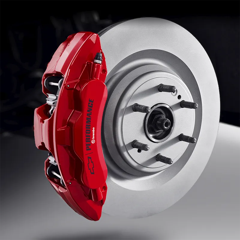
I had to buy parts anyways so I went with a set of 2010+ GMT900 Calipers, pads, rotors and brake hoses to upgrade to the 13" rotors instead of 12". There's probably better choices out there for brake hoses as these required some messing around to make the mounts and completely re-doing the hard lines. I think the 4x4 guys are running stock GMT400 hoses which are long enough to reach the stock position on the frame.

I have not driven on this setup yet as I have tons of work to do on the rest of the truck but figured I'd post this as it seems to be a topic that perpetually floats around. I have fully cycled the steering and suspension to verify clearance, I had a fender with a rolled lip in place. The tie rods get very close to the sway bar, I may make longer end links to create a bit more clearance. The sway bar is aftermarket, I think Belltech and it has 2" lowering coils. I should also note that I just cut the leads off of the ABS sensor, but left the sensor plugged into the spindle to help keep moisture out.

I should also note that I didn't go with GMT800 2WD spindles as the lower ball joint would need to be flipped to fix the ride height and upper control arm angle. Doing this would require a larger stud on the ball joint to get proper engagement. The Astro spindle let me just ream it out a little larger than stock and re-use the stock GMT400 lower ball joint.


GMT400 Spindle (left) beside Astro Spindle (right)
You must be registered for see images

Installed
You must be registered for see images

You must be registered for see images

Full compression with the wheel turned
You must be registered for see images
Nice!!

FYI there is nothing stopping you at that point (other then wheel clearance) from doing the 2019+ 4 piston 13.5" rotor brake swap...

https://www.gm-trucks.com/forums/topic/224640-19-silverado-front-brake-upgrade/
 

Supercharged111

Truly Awesome
Joined
Aug 20, 2015
Messages
12,760
Reaction score
15,593

TheAutumnWind

I'm Awesome
Joined
Feb 11, 2019
Messages
698
Reaction score
740
Location
California
I didn't realize this was a thing. Those are some beefy brakes. Probably need 18" or bigger rims to clear?
Yeah I only found out about it recently. Unfortunately there was no info on it when I did the NNBS upgrade on my NBS Escalade last year or I would have gone this route. Love that this is something readily available at autoparts stores. I wish the 2wd gmt400 to gmt800 conversion was a little bit more straightforward.

In this thread they are shipping around a caliper so that guys can verify wheel fitment on different trucks:


"Thanks! Ended up finding that information a few pages back. With my High Country spoke design it looks like I have a TON of room. One member posted the measurement from the caliper mounting flange to the caliper face hump is about 4 7/8". I have about 5.5" of clearance.

Offset is only part of the equation I guess."

"Very true. It’s also the shape of the backside of the spokes. It depends on if they curve outward and how much."

"This guy did it.
Fit on 17s no spacers
He says silverado yukon tahoe subburbs
xc_hide_links_from_guests_guests_error_hide_media

I had a friend at a dealer pull the part numbers for the silverado brakes.
I priced them out at GMPartsdirect.com.

I have NOT validated the install of these parts but from the schematic they look to be correct
Washers for caliper alignment not included.
I don't know if the splash shields will fit.

2021 Silverado Brake Swap List
Description Part# Price
Caliper Front Right 13536580 81.08
Caliper Front Left 13536579 81.08
Splash Shield Left 84080138 8.83
Splash Shield Right 84080137 8.83
Front Rotor 13514522 82.73 ....13.5" rotor
Front Rotor 13514522 82.73
OEM Pads 84847749 108.04
Disc Brake Pad Pin Kit 13513399 6.35
Total 466.02"
 

Shwa Kid

Newbie
Joined
Jun 9, 2021
Messages
29
Reaction score
47
Location
Canada
I didn't know about the 4 pot calipers, they're not even that expensive if you can find them. I'm pretty confident what I have will be pretty sufficient given tire choices in truck sizes and a moderately lighter vehicle that will never haul anything, but we'll see (if I had to buy everything still I'd probably go that route).

CCreddell, unfortunately that's not the case for the tie rod issue. If you picture how your front suspension cycles, the wheel hub travels in an arc (this can be simplified for learning purposes by ignoring the upper control arm and looking at the sweep of the lower control arm). What causes bump steer is when the tie rod doesn't travel in the same arc as the hub. In an ideal simplified case, the tie rod is the same length as the lower control arm, and they're both on the same angle. Say the LCA starts horizontal, it rises and starts to come inwards towards the frame, and the tie rod does the same, keeping the wheel pointing in the same direction. In a moderately bad case, they're not on the same angle, so as they cycle, they're not on the same part of the sweep causing the ball joint pivot and the outer tie rod pivot to travel closer to the frame at different rates, causing the wheel to steer a little. In a nightmare situation, they actually cross (say tie rod points down while lower control arm is horizontal), this causes the outer tie rod to move out relative to the frame, while the lower ball joint moves inwards, causing crazy amounts of steering, and over the course of the travel it could cause the wheel to steer outwards, then inwards. All this is simplified and the geometry gets more complex when you add in the upper control arm, but that's the principle of it)

This nightmare case was pretty much what I was seeing before flipping the ball joint (over the course of full droop to full compression, wheel would point outwards, then inwards). If you look at your truck, there's basically 4 points to consider for bump steer geometry (staying simplified, not considering upper control arm): your inner tie rod pivot, outer tie rod pivot, inner lower control arm pivot and lower ball joint. If you look at the height of your inner tie rod vs your lower control arm pivot, it's significantly higher. Looking at the stock van spindle, the lower ball joint and outer tie rod are at approximately the same height, by flipping the outer tie rod, I got the lower control arm geometry (line from pivot to ball joint) pretty much parallel to the tie rod.

When you lower your truck, you basically move the wheel hub upwards relative to the frame, meaning your ball joints and tie rods move together just like your suspension is normally cycling, so the geometry isn't changed by lowering (unless you change the length of your control arm). I would say there's one way it might work out okay (not ideal) is that if by lowering more you get past the point where your tie rod want's to push out while your ball joint pulls in, so you get down from "nightmare" to "moderately bad", which I think is where the trucks were stock TBH. Another option would be to lower the center link. Maybe there's one that would work that has the tie rod holes lower than the pitman and idler arms, but that could flex (same with those banana shaped tie rods). Lowering idler and pitman arms doesn't seem to be a reasonable option, you'd have to modify the frame and lower the sway bar. Personally, I'd just notch the frame for the tie rods, it's outside of the suspension points and carries relatively little load.

Hopefully that clears it up... there's probably better write ups with diagrams if I didn't explain it well.
 
Last edited:

99bluetahoe

OBS Enthusiast
Joined
Jan 5, 2010
Messages
65
Reaction score
78
There is even the new 2021 PPV Tahoe 6 piston calipers with 15" rotors that might work as well. I have been curious to gather some of those parts and try them on my 2 door tahoe. I already run the gmt800 spindle with 2008 silverado brakes.
 

ccreddell

I'm Awesome
Joined
Aug 6, 2010
Messages
1,253
Reaction score
200
Location
Medford, OR.

At $2000+ Im thinking the 13" rotor and 4-piston caliper would be enough for me....
 

Latest posts

Forum statistics

Threads
64,352
Messages
1,391,935
Members
51,472
Latest member
Jake rogers
Top