Thank you for that information
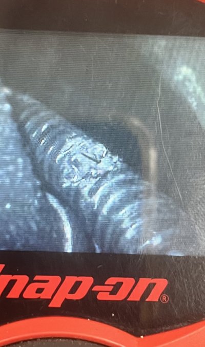
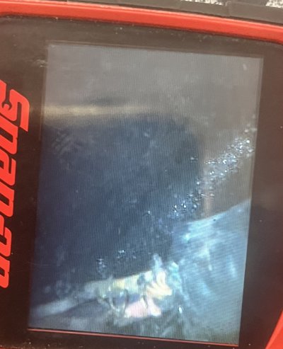
I had some time to dig into it and I found the open in the ground to the B2S1 circuit.
Looks like a rodent or a rub through
Now to get to that spot to fix it
Good find, and thanks for sharing what you discovered!
Each failure that is troubleshot, fixed, &
shared for everyone's edification is another
piece of the puzzle that, in total, gives us all a clearer picture of what it takes to keep
these GMT400s on the road literally decades after they were made.
****
Of course
@east302 and
@L31MaxExpress were on the money with both the schematics
& the physical location of the ground for the O2 sensors. Myself, coming up to speed on
the General's way of documenting the wiring harness was tough sledding at first. So many
grounds and Connectors seemingly scattered about willy-nilly, both physically & numerically?
There's gotta be some some sort of rhyme or reason?
But then I discovered the following big picture in the Wiring Diagrams section of the '99 C/K Service Manual:
Refer to Volume 4, Section 8, page 326:
You must be registered for see images attach
Voila! This really helps me while I'm trying to translate the abstract data from the wiring diagram to the physical layout
on the truck! Between this 'Truck Zoning' picture, the drawings of each ground & Connector location, and the
very clear pinouts...after wading around in it a bit I find the electrical wiring harness documentation to be better
than I hoped -- little to no guesswork involved. Simple is good, especially for an old dog like myself. :0)
Hope fellow up & coming sparky types find this helpful...