Ignition switch wiring

Disclaimer: Links on this page pointing to Amazon, eBay and other sites may include affiliate code. If you click them and make a purchase, we may earn a small commission.

702castillo

Newbie
Joined
Aug 21, 2023
Messages
11
Reaction score
4
Location
Las Vegas
so I see the purple starter wire is going too a panel slot number 6 but is that going too be my convenience box or the fuse box?? I’m going too put my yellow wire back too the clutch switch also! Thank you so much for all the help and patience trying to diagnose this issue remotely man!!
 

GoToGuy

I'm Awesome
Joined
Sep 16, 2020
Messages
3,143
Reaction score
3,694
Location
CAL
Purple wire is from starter to the convinece center plug in engine bay below brake booster. It's connector # C100. Pin slot or hole #6. The half in engine bay. The other side is in cab above your feet. There like bookends. The purple is in hole #6. Look at it, it's a map , it shows where. The through the bulkhead connector, aka convinece center #6 hole purple in cab.
 

702castillo

Newbie
Joined
Aug 21, 2023
Messages
11
Reaction score
4
Location
Las Vegas
It’s a little hard too see but non of the slots have numbers on them for #6 or #c100 and also they go by color but non of them say PPL so I’m at a loss and also I can’t even get the connections out of the ignition switch too replace it and can’t find a thread or video explaining how too replace it so I just feel stuck about the whole issue. I tried too pump the clutch too see if by chance it was the clutch switch but still got nothing from it
 

Attachments

  • IMG_2303.jpeg
    IMG_2303.jpeg
    340.8 KB · Views: 6

Road Trip

Supporting Member
Supporting Member
Joined
Jul 8, 2023
Messages
1,122
Reaction score
3,204
Location
Syracuse, NY
It’s a little hard too see but non of the slots have numbers on them for #6 or #c100 and also they go by color but non of them say PPL so I’m at a loss and also I can’t even get the connections out of the ignition switch too replace it and can’t find a thread or video explaining how too replace it so I just feel stuck about the whole issue. I tried too pump the clutch too see if by chance it was the clutch switch but still got nothing from it

@702castillo ,

Please stand by.

I'll pull together some info I've got and we'll do our best to put you in control of this troubleshooting situation. Will be back asap!
 
Last edited:

Road Trip

Supporting Member
Supporting Member
Joined
Jul 8, 2023
Messages
1,122
Reaction score
3,204
Location
Syracuse, NY
The first thing we need to do is completely understand the ENTIRE path
of the ONE circuit that is used to give the driver the ability to rotate the
engine on command while sitting behind the steering wheel. This may sound silly,
but we need to verify every single inch (either visually, or with a meter, or by temporarily
jumpering around suspect parts) ...of this 1 unique 'crank' circuit.

To get the info we need, we first go to the '91 C/K Service Manual and locate the Power Distribution page:


You must be registered for see images attach


Believe it or not, everything you need to know about your CRANK circuit is in there somewhere.

Listen, trying to figure this page out while at the same time trying to troubleshoot a broken physical
circuit on your truck is tough sledding, even for people that have experience doing this.

The answer (just like always) is to divide and conquer.

1) The first thing I always do is draw out the circuit I need to troubleshoot by hand.

2) THEN I use my custom troubleshooting roadmap to navigate my way through the physical wiring harness.

****

In my next post I will upload my hand drawn schematic of this circuit. Please stand by...
 
Last edited:

Road Trip

Supporting Member
Supporting Member
Joined
Jul 8, 2023
Messages
1,122
Reaction score
3,204
Location
Syracuse, NY
Just in case you still needed help after your post last Thursday, I decided to
familiarize myself with your circuit. In the process I learned that the '88-'94
crank circuit solenoid current is wired directly through the Ignition Switch, which
is different than the use of the Ignition Switch using low current to control a
underhood Starter Relay in the '95+ GMT400s, so my (much better drawn)
'99 C/K manual was of no help.

Therefore, I went back to the '91 C/K manual and found that Power Distribution
page I shared above. Ugh, what a convolution!

So I decided to redraw just the circuit that we need to work. Here is my interpretation:

The entire "Crank" circuit: from Battery + > Junction Block > C100 > C255 > Ignition Switch > C255 > Clutch Switch > C100 > Starter Solenoid > Ground.
You must be registered for see images attach


Using the above, try to find/follow this circuit in the Power Distribution page from the '91 C/K Service Manual. IF you find a mistake, don't hesitate to
point this out. So far what I've drawn has had only 1 set of eyes on it. 2+ sets of detail-oriented eyes are always preferable. Trust But Verify.

****

In my next post I will share a page with some physical component info on it.

Be back shortly.
 
Last edited:

Road Trip

Supporting Member
Supporting Member
Joined
Jul 8, 2023
Messages
1,122
Reaction score
3,204
Location
Syracuse, NY
It’s a little hard too see but non of the slots have numbers on them for #6 or #c100 and also they go by color but non of them say PPL so I’m at a loss and also I can’t even get the connections out of the ignition switch too replace it and can’t find a thread or video explaining how too replace it so I just feel stuck about the whole issue. I tried too pump the clutch too see if by chance it was the clutch switch but still got nothing from it

Alright, we'll tackle these one at a time.

On page 6/193 of the '91 Electrical Wiring Manual
they give the troubleshooter a chart showing what abbreviations = what colors
that the wires are. (ie: You won't see 'PPL' printed anywhere.)

You must be registered for see images attach


Here's a Physical Connector picture for C255 & C256:

You must be registered for see images attach


And finally, just to give you the troubleshooter a Big Picture of the wiring harness in order
to help figure out where you physically have to go in order to find the components listed on
the schematic diagram, the manual gives you this:

You must be registered for see images attach


Alright. I'll pickle this and then start writing up a troubleshooting plan of attack.

Be prepared for me to emphasize SAFETY in my next post. We are NOT going to do anything
without *
first* ensuring that if the starter spins, the truck transmission is in NEUTRAL.
First time, 27th time, the last time. You will verify that the truck
has been made safe before troubleshooting.

Thank you. :)
 
Last edited:

Road Trip

Supporting Member
Supporting Member
Joined
Jul 8, 2023
Messages
1,122
Reaction score
3,204
Location
Syracuse, NY
Before we continue to delve into this circuit, I'd like to stop and just talk our
way through a quick troubleshooting Sanity Check. Why?

A: Few things are more embarrassing than going through a huge troubleshooting
effort, only to find out that a Simple (yet wrong) Assumption was made at the outset? And usually
this is discovered by someone not involved, who just happens to touch something that
is of no interest to the troubleshooters...but it magically starts to work?

In addition, troubleshooting remotely means that it's easy for you to see/know
something that I don't, and then I make assumptions based upon what has AND
what hasn't been said...and we're off, down the garden path.

****

OK, now that I've set the table, here are the possible reasons why your truck
intermittently won't crank over, listed in order of probability:

1) You have a battery that can't supply enough continuous current to make a good starter
work as advertised.

2) You have a bad starter and/or starter solenoid, and all wiring/switches/grounds are good.

3) You have a good starter, but there is marginal/intermittent connection in either this circuit's High Power, Ground, or Control WIRING or CONNECTIONS.

4) After tens or hundreds of thousands of cycles, a moving human operated switch has reached the end of it's reliable service life,
and can no longer provide the FULL Electrical Conductivity required to support the proper operation of the starter solenoid.
(Ignition Switch, Clutch Start Switch)

5) A previous owner has repaired/modified/hacked the Power or Control electrical circuit. (Due to prior collision repair, anti-theft device installation, etc.)
NOTE: A lot can happen to a vehicle since it was manufactured in 1991. (!)

****

In English, the assumption has been made that the battery, starter, and high-current connections are all good.

Advance Auto & some of their competitors will performance check your battery & starter for FREE. If you are
absolutely sure that they are Good to Go, then proceed. If you have any doubt whatsoever, then have them
both tested so that any troubleshooting done afterwards in on top of a good foundation.

This is a decision that I will leave up to you, for all this is in your sphere of influence.

****

In my next post, I am going to lay out a 'Building Block' approach to troubleshooting the Crank Control Circuit.

And in order to do what I am going to propose, we will need one of the following: (Similar but not Identical is OK)

You must be registered for see images attach


More to follow.
 
Last edited:

Road Trip

Supporting Member
Supporting Member
Joined
Jul 8, 2023
Messages
1,122
Reaction score
3,204
Location
Syracuse, NY
For completeness, at this time I am going to share the two 'Cranking' Troubleshooting
Flows provided by the '91 C/K Electrical Wiring Manual:

Note: Page 47/193 of the.pdf file = physical page 44.
You must be registered for see images attach


That's it. All the troubleshooting that the '91 Service Manual provides for cranking issues is on this single page. (!)

Take a moment & read through the Diagnosis charts. Can you see what part(s) are NOT called
out for troubleshooting/possible replacement? (Hint: They call out a fuse that isn't involved?
Meanwhile, what isn't mentioned is the Fusible Link on the feed between the Battery Junction Block and
terminal/pin #2 of C100?)

One last thing. Whenever you read a Service Manual, always keep in mind the assumptions that
the writers of that manual had to make in order to write a book that wasn't the size of a library.
(From the General's perspective, the primary goal of this manual is to help speed the dealership
technician through a warranty repair.)

Sure, it was also used to fix a customer's car post warranty, but I'll bet you a dollar that the person
writing this section assumed that the wiring was not hacked by the car owner in order to install a kill switch?)

In other words, the manual is written to cover 90+% of what could be reasonably expected to fail
on a recently built '91 GMT400. I am a big fan of the factory manuals, but there are limits to everything,
and a good troubleshooter keeps this in mind while using these reference materials.

Find yourself troubleshooting a '91 truck in 2023?
Toto, we're not in Kansas anymore. :0)

****

IF you have an electrical mentor working with you in person on the problem, then at this time you could
have them guide you through the troubleshooting chart, performing those checks. But in the next
(& final) post I am going to propose that we absolutely minimize the variables and take positive
control of this circuit.

More in a minute.

****

(OPTIONAL READING targeted to the electrical devos in the audience.)

I'm pretty sure that I found an error in Step #4 in the 'No Crank' troubleshooting flows.
They have you jumper around the Clutch Start Switch, and if there's a No Crank, then
they have you check the 5 amp "CRANK" fuse. Sounds reasonable, right?

Try as I might, I could NOT make this fuse the source of the power used to drive the
starter solenoid in the Power Distribution diagram. (It's not even big enough to handle
the starter solenoid current draw?)

I finally found the answer in the main manual, in the section covering the ECM. This 5 amp
fuse protects the wire that's spliced into this circuit in order to communicate to the ECM
that the engine is being cranked, and that extra enrichment + no diagnostics is called for.
(See attached.)

I include this not for the OP's situation, but for future reference in case anyone else makes it
this far into this thread.

Are we having fun or what? :)
 

Attachments

  • '91 CRANK fuse to ECM (1994)_DRIVEABILITY_EMISSIONS_ELECTRICAL_DIAGNOSIS_MANUAL.jpg
    '91 CRANK fuse to ECM (1994)_DRIVEABILITY_EMISSIONS_ELECTRICAL_DIAGNOSIS_MANUAL.jpg
    111 KB · Views: 15
Last edited:

Road Trip

Supporting Member
Supporting Member
Joined
Jul 8, 2023
Messages
1,122
Reaction score
3,204
Location
Syracuse, NY
OK, after all the build up in Posts #14 thru #19, it's finally time to take all
that troubleshooting setup and start proving/disproving each part in this
series circuit.

****

When it comes to an electrical series circuit, I'd like to use a simple mechanical analogy:

"A chain is only as strong as it's weakest link."

But before we start troubleshooting, as promised in Post #17, I am going to
emphasize Safety. Why? A: Because we are going to troubleshoot the
starter in a Go / No-Go method. Workie? Or No Workie?

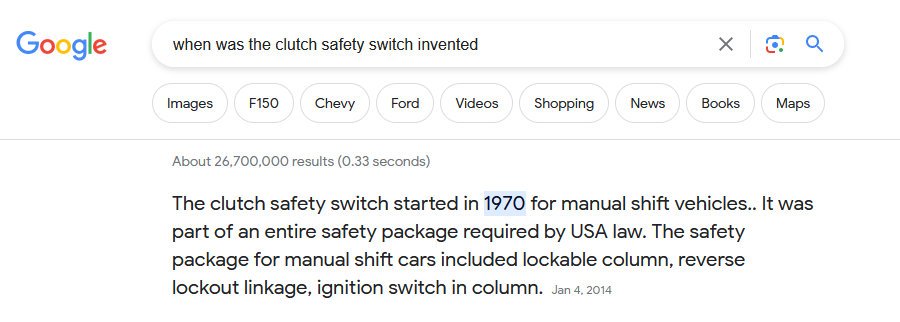
In English, we are going to jumper battery voltage to the starter solenoid. And ever
since the Clutch Safety Switch was mandated ~50 years ago, people no longer realize
that an engine can be started in gear, and mayhem can occur, especially when nobody
is behind the wheel. (!)

Given this, before we proceed, YOU SHOULD:

1) ENSURE that the transmission is in Neutral.

2) The Parking Brake is fully applied. And Chock the wheels. (Chocks are cheap money at Harbor Freight.)

3) NOBODY (including YOU) are in front of or behind the truck.

4) DO NOT do this while under the vehicle, or standing on your head under the dash.

NOTE: If you can involve a friend, then have them apply the brakes firmly during testing.

Bottom line, simply be smart, and you will be fine.

****

Troubleshooters will refer to this method as a Binary Search. Others call this a half-split method.
Purists like to eliminate as much as possible per test. But I simply recommend that you test
in whatever sequence that gives YOU the most confidence in your diagnosis.

Step #1: Let's prove that the starter & starter solenoid are good.

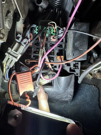
* With the truck SAFED, disconnect the purple wire from the starter solenoid. Connect one end
of the fused-protected jumper wire where the purple wire was connected, make sure that you are
out of the way, and apply battery voltage to the other end of the jumper.

* Starter spins over? Starter good. Do it 2 or 3 times -- make sure the first success wasn't a fluke.

* Starter stays silent? Recheck the big current connections. Then pull the starter and have it tested
for free at the nearby auto parts store. Keep working Step #1 until when you jumper battery voltage
to the starter solenoid that the engine always spins over.

Step #2: Troubleshooting the Control Circuit:

* Now that the starter/starter solenoid combo is tested good, reconnect the purple wire to the starter
solenoid & attempt to start the truck normally. Now engine turns over on command? Great. Done.

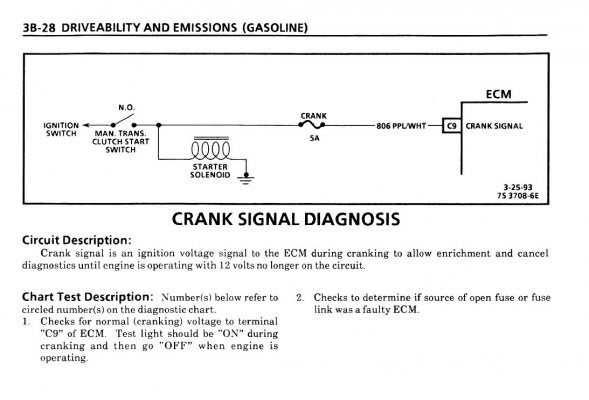
* Truck still doesn't start? Now what we are going to do is use our fused jumper to apply power to
our control circuit, eliminating one link of the chain after another. (refer to that diagram I drew in Post #16.)

For example, I could connect the jumper to pin #5 on the Clutch Start (Safety) Switch, depress the clutch
pedal, and then apply battery voltage to the other end. (Note: A helper would make this a lot easier.)

* IF the starter now spins, then the clutch switch has continuity, and we need to look upstream at the
Ignition Switch. And you keep going back until you find the open in the circuit. (PO's Kill Switch? Other
damage to the harness? Etc.)

****

Anyway, that's my take on this. The beauty of Step #1 is that we not only prove that the starter/starter solenoid
is good, but we also prove the high current side of the equation. AND in addition we prove that our test setup
is valid & can be relied upon. I find that once I can *make* the starter spin on my command, then I gain the
confidence that I'm going to figure this out. And ultimately, that's all a troubleshooter really needs, is that
they can narrow down the failure to something that can be repaired or replaced.

****

The funny thing is that once you start the divide & conquer troubleshooting process, it will probably take
you less time to perform these tests than it did to wade through all this blah blah blah.

Unfortunately, when it comes to troubleshooting a circuit with several parts, each part relying on the
previous section(s) feeding it, you kinda have to know everything before you can figure out anything.

And maybe this helps to explain why people who troubleshoot electrical stuff are just a little off of the
beaten path, if you know what I mean? And I've met crackerjack mechanics who could really swing a
wrench, but at the same time wanted nothing to do with electrical stuff. And I've also worked with
electronic wizards who couldn't install a serpentine belt to save their lives. But IMHO somewhere in
the middle of those 2 extremes is where you want to end up.

And outlasting this "No Crank" issue will be a great step towards that goal.

Let us know what you find. And please be SAFE while you are busy finding it.

Thank you. :)
 

Attachments

  • when was the clutch safety switch invented - Google Search.jpg
    when was the clutch safety switch invented - Google Search.jpg
    70.9 KB · Views: 12
Last edited:
Top