It’s a little hard too see but non of the slots have numbers on them for #6 or #c100 and also they go by color but non of them say PPL so I’m at a loss and also I can’t even get the connections out of the ignition switch too replace it and can’t find a thread or video explaining how too replace it so I just feel stuck about the whole issue. I tried too pump the clutch too see if by chance it was the clutch switch but still got nothing from it
Alright 702castillo, we've covered some ground. I just reviewed this thread, and I wanted to clarify/differentiate the parts that are all
intertwined, with the hope of helping you more easily navigate the physical wiring harness while following the magic 'crank' circuit.
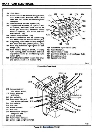
1) Let's discuss your photo first. You have taken a picture of the "Convenience Center", which (from the photo perspective) is
on top of the C100 firewall pass-through that the crank circuit wiring is routed between the cab and the engine bay. (Refer to
Figure 23 in the 1st attachment for a drawing of the Convenience Center.) If you study the electric circuits that the
Convenience Center supports,
none of them are related to the starter solenoid 'crank' circuit.
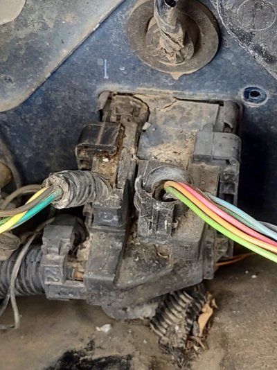
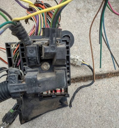
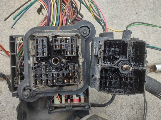
2) I went out to my own truck and took a quick look at the Convenience Center under the dash, and it wasn't intuitive at to how
it came out. I couldn't really find anything in the manual, so I searched the GMT400 forum, and discovered that
@Martin Evans
had a similar age GMT400, and had figured out how the C100/firewall/Convenience Center sandwich could be disassembled...and
then was good enough to share the wealth. (See attachments #2, #3, & #4 -- tip of the hat to Mr. Evans.

)
For additional info on C100 + Convenience Center servicing, head over to that thread
HERE.
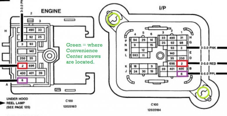
3) In the last attachment, I zoomed in on the C100 picture in the center of the power distribution page shown in post #
15 above.
I color-coded the C100 terminals involved in the crank circuit, and also showed where the the screws seen in Mr. Evans' photos go.
Lastly, the C100 connector is shown both from the "Engine" (bay) and "I/P" (Instrument Panel) sides. If you were to print this out
and then fold the paper vertically in half like a book, then it's easier to visualize what they are trying to show the troubleshooter.
****
Hopefully all of the above will help to clear up the confusion between the photo you shared and where the circuit we need to
troubleshoot actually traverses the firewall, both power coming in, and then the human-driven control signal out of the cab.
Having shared all this, I would caution against just tearing all this apart
unless you have definitely troubleshot the
problem to this specific area. We're getting pretty close to the dilithium crystals in a '91 GMT400's wiring harness. :0)
Happy Hunting --