Brake Lights only work when the ignition is off / Fuel Gauge not reading.

Disclaimer: Links on this page pointing to Amazon, eBay and other sites may include affiliate code. If you click them and make a purchase, we may earn a small commission.

zopples

Newbie
Joined
Apr 8, 2024
Messages
2
Reaction score
0
Location
Houston, TX
Howdy, I'm Caleb. I've got a 1995 Chevy C1500 with a recently swapped 5.7, refurbished motor, all new accessories, radiator, sensors except speed sensor and oil pressure sensor.

The brake lights don't work when the ignition is turned to the accessory or on positions, only when in the off position. This only happened recently. I didn't think it was the brake light switch but I went ahead and replaced that. I've also got some tail lights and new boards coming in as a friend of mine suggested the boards on my tail lights went bad. I've read elsewhere that it could be an issue with the ignition switch but I'm curious if anyone could elaborate on that?

My fuel gauge was working but read off by about 1/4 of the tank, it would read 3/4 of a tank when it was full. I ran it down near to empty on the gauge but I still had about a 1/4 of a tank left and when I refilled my truck the gauge shot past full. Now when the truck is off it will drop past empty and stay at past full when it's on. New gas tank, fuel pump, and sending unit.

If anyone has any idea what these issues could be caused by, please give me a hand here! Thanks!
 

JOHNGAAA1

I'm Awesome
Joined
Sep 13, 2021
Messages
390
Reaction score
555
Location
11590
There are 2 grounds under the left rear bumper. 1 for the sending unit and one for the tail lights. Start there.
 

GoToGuy

I'm Awesome
Joined
Sep 16, 2020
Messages
3,143
Reaction score
3,694
Location
CAL
Did you text the out put on the new brake switch?
 

Road Trip

Supporting Member
Supporting Member
Joined
Jul 8, 2023
Messages
1,122
Reaction score
3,207
Location
Syracuse, NY
Howdy, I'm Caleb. I've got a 1995 Chevy C1500 with a recently swapped 5.7, refurbished motor, all new accessories, radiator, sensors except speed sensor and oil pressure sensor.

Howdy Caleb, and Welcome to the GMT400 forum. Based on your problem description, I opened
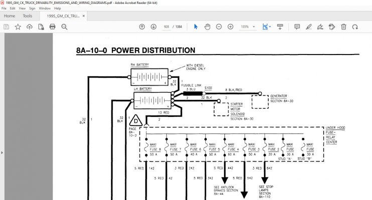
up the '95 FSM (Factory Service Manual) and dug into the brake light circuit. In other words, the
diagrams I'm going to share are all from the '95 FSM, and should be relevant.

The brake lights don't work when the ignition is turned to the accessory or on positions, only when in the off position. This only happened recently. I didn't think it was the brake light switch but I went ahead and replaced that. I've also got some tail lights and new boards coming in as a friend of mine suggested the boards on my tail lights went bad. I've read elsewhere that it could be an issue with the ignition switch but I'm curious if anyone could elaborate on that?

OK, after reviewing the wiring diagrams it looks to me that the Ignition Switch is not directly involved
in the Brake lights. (aka: 'Stop lamps' in the GM service manual.) However, the symptoms you described
would make a troubleshooter think that the Ignition Switch is somehow involved. And it is, thanks to the
fact that GM has interleaved both the "Turn Signal" and "Hazard Flasher" functions on top of the simple
ON/OFF brake light signal. This slicing and dicing is done in the Multifunction Switch, and as long as everything
works to factory specs this all interoperates seamlessly. (!)

NOTE: I am a big fan of the General's service manuals, and especially the documentation of the wiring harness...but
on occasion the person drawing the circuit tried to fit too much detail onto a single page, and it makes
a troubleshooting session harder than it needs to be. IMO, a troubleshooter would draw the multifunction switch
at least 3 times.

Mode 1: Brake input only.
Mode 2: Turn signal overlaid onto Brakes only.
Mode 3: Hazard Switch / Emergency Flashers only.

If they did this, the troubleshooter could go through the different modes, observe the switch changes between modes,
and have a good grasp of how the circuit really works.

Instead, they show everything at once. Not very helpful. To cap it off, you have to chase signals across at least 3
different pages. So in the interest of troubleshooting, I decided to draw only the BRAKE inputs and outputs on a single page:

You must be registered for see images attach


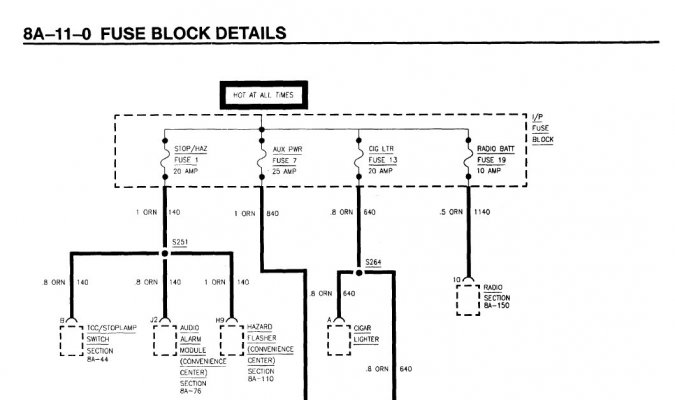
I've cross-checked the above against the FSM, and I'm 99% sure the above is accurate. From Reply #3 you have verified
ground G410 on the bottom of the page. I'm assuming that because the Brake Lights are working with Power off that the
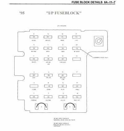
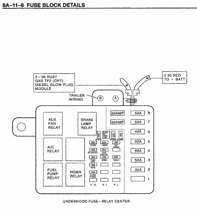
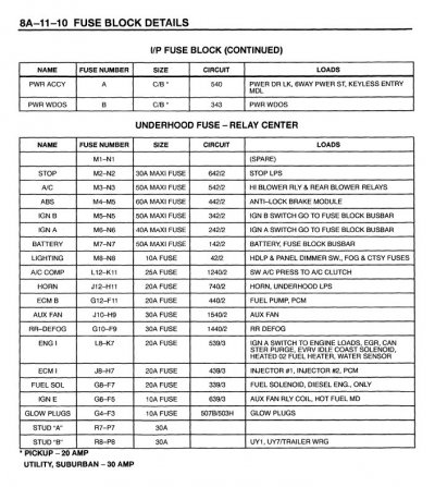
20A 'Stop/Haz'
Fuse 1 at the top of the page is good, but it won't hurt to check. (See attachments #1 & #2)

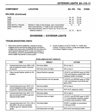
You have already replaced the Stoplamp/TCC (aka: Brake Light) switch, so when you depress the brake pedal the +12V
from Fuse 1 traverses the Brake Light switch, and via the White wire travels to pin 17 on Connector 266, where it enters the
Multifunction Switch. And when everything is off, you should see that same +12V at C266 pins 18 (Yellow) and 19 (Dark Green),
which in turn travel from the steering column to the LEFT and RIGHT brake lamps via Connectors C112 & C400.


As a troubleshooter, with the key in the off position you should be able to disconnect C266, and jumper pin 17 to 18, followed
by pin 17 to 19, and while operating the brake pedal verify that the brake lights come on. If it was me, I would then turn the key to
on, and verify that while I am still jumpered around the multifunction switch the brake lights still work, power on or off, as they are
supposed to.

IF they do, then by temporarily removing the multifunction switch from the brake circuit we have fixed the symptom. And to prove this,
if you turn the key OFF and reconnect everything, I would assume that your problem will return. By doing all this you can prove to yourself
that the switch is the culprit prior to buying another one. (!)

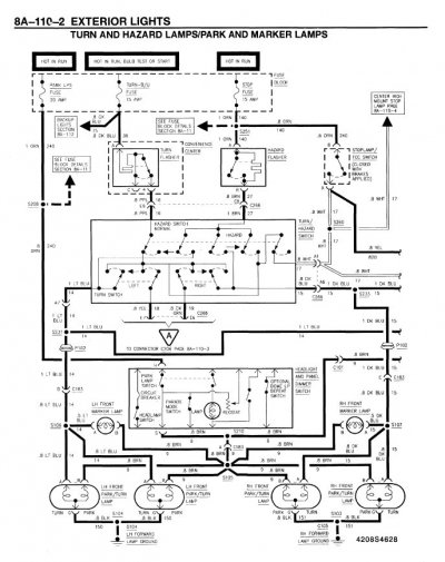
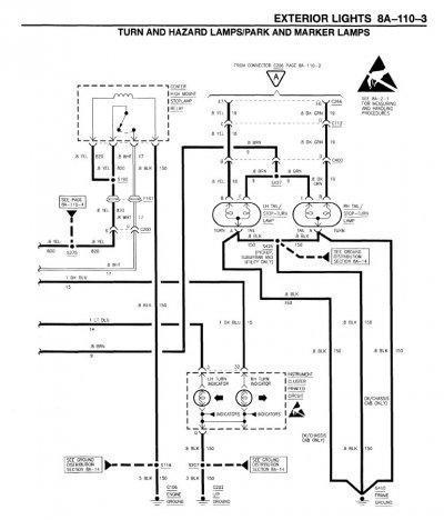
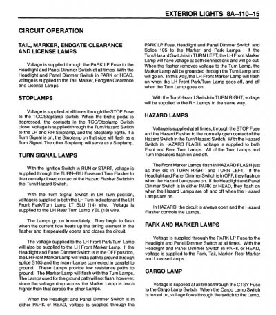
For what it's worth, in the 3rd and 4th attachments are pages 8A-110-2 & 8A-110-3 from the '95 FSM,
and in these 2 pages you will see the Stoplamp/TCC (Torque Converter Clutch) switch feeding into the
multifunction switch, as well as the wiring back to the Stop Lamps.

****

Don't know how much you have explored this forum, but there's a a cache of Factory Service Manuals that are
free for the downloading, so that you can take these troubleshooting hints and use them to really dig into your
problem circuit. If you follow this LINK it will take you to where you can find the '95 FSMs that I was using above.

****

I know that we covered a lot of ground, but I wanted to show you that the brake light circuit does not travel through
the Ignition Switch...but at the same time if there's some sort of failure involving a Key On powered circuit in the
multifunction switch that is interleaved with the brake light function then this might explain the failure symptoms
you are observing.

Hope this has provided some insight on how the circuit is documented to work.

Let us know what you find.

Cheers --
 

Attachments

  • '95 Stop Haz Fuse 1 Hot at all Times - 1995_GM_CK_TRUCK_DRIVABILITY_EMISSIONS_AND_WIRING_DIAGR...jpg
    '95 Stop Haz Fuse 1 Hot at all Times - 1995_GM_CK_TRUCK_DRIVABILITY_EMISSIONS_AND_WIRING_DIAGR...jpg
    71.2 KB · Views: 6
  • '95 IP fuseblock (marked up) --1995_GM_CK_TRUCK_DRIVABILITY_EMISSIONS_AND_WIRING_DIAGRAMS.jpg
    '95 IP fuseblock (marked up) --1995_GM_CK_TRUCK_DRIVABILITY_EMISSIONS_AND_WIRING_DIAGRAMS.jpg
    89.7 KB · Views: 5
  • '95 8A-110-2 turn hazard switch -- 1995_GM_CK_TRUCK_DRIVABILITY_EMISSIONS_AND_WIRING_DIAGRAMS.jpg
    '95 8A-110-2 turn hazard switch -- 1995_GM_CK_TRUCK_DRIVABILITY_EMISSIONS_AND_WIRING_DIAGRAMS.jpg
    126.8 KB · Views: 7
  • '95 8A-110-3 brake lights - 1995_GM_CK_TRUCK_DRIVABILITY_EMISSIONS_AND_WIRING_DIAGRAMS.jpg
    '95 8A-110-3 brake lights - 1995_GM_CK_TRUCK_DRIVABILITY_EMISSIONS_AND_WIRING_DIAGRAMS.jpg
    99.7 KB · Views: 6
Last edited:

Road Trip

Supporting Member
Supporting Member
Joined
Jul 8, 2023
Messages
1,122
Reaction score
3,207
Location
Syracuse, NY
For completeness, I thought that I'd add the Stop Lamp circuit theory of operation as well as
the troubleshooting flow given by the '95 FSM.

Attachment #1 is the Stop Lamps circuit theory.

Attachment #2 is the "Stoplamps do not Operate" troubleshooting procedure.

****

NOTE: One thing I could not nail down to my complete satisfaction is the exact relationship (if any)
between a 30A Maxi-fuse #2 in the Underhood circuit breaker panel and the Stop/Haz fuse
in the IP (Instrument Panel) mentioned in the last reply.

Attachment #3 is the Underhood Fuse Panel.

Attachment #4 is the Underhood load assignment by fuse.

Attachment #5 is the Underhood Power Distribution diagram.

In other year manuals I can find the wiring diagram documenting the feed
between the Underhood Fuse Panel and the Instrument Panel, but in this manual
there's nothing that I was able to dig up.

One thing that I am confident in is that the brake light function is available 100% of the time,
and whichever circuit is feeding it is definitely "Hot at all Times". (Note: In the previous reply, at the top of
p. 8A-110-2 there is an erroneous "Hot in Run" shown above the Stop/Haz fuse -- that should
be "Hot at all Times". But at the same time it *is* correct in the 1st attachment: p. 8A-11-0 "Fuse Block Details".

That's all I got. But if you take all of the above, download the '95 manuals, and get out a trusty voltmeter you
should be able to figure why this circuit isn't working properly no matter what position the Key is in.

Sometimes the FSMs are airtight. But as can be seen elsewhere in the forum, the multifunction switch is not
as well documented as it could have been. Who knows? You might disconnect all the connectors in this circuit
for troubleshooting, and once you put them all back together everything straightens up and flies right? (Wouldn't
be the first time something like this happens.) Or you take a look at the multifunction switch and it's half melted,
and all bets are off.)

The bottom line is to definitely troubleshoot this area carefully before replacing any parts, for if you
replace a good original part with a substandard aftermarket part, it's possible to make the situation worse
instead of better.

Best of luck --
 

Attachments

  • '95 Stoplamps circuit description - 1995_GM_CK_TRUCK_DRIVABILITY_EMISSIONS_AND_WIRING_DIAGRAMS.jpg
    '95 Stoplamps circuit description - 1995_GM_CK_TRUCK_DRIVABILITY_EMISSIONS_AND_WIRING_DIAGRAMS.jpg
    221.9 KB · Views: 5
  • '95 'Stoplamps do not operate' FSM diagnosis 1995_GM_CK_TRUCK_DRIVABILITY_EMISSIONS_AND_WIRING...jpg
    '95 'Stoplamps do not operate' FSM diagnosis 1995_GM_CK_TRUCK_DRIVABILITY_EMISSIONS_AND_WIRING...jpg
    168.1 KB · Views: 5
  • '95 Underhood Fuse Block --1995_GM_CK_TRUCK_DRIVABILITY_EMISSIONS_AND_WIRING_DIAGRAMS.jpg
    '95 Underhood Fuse Block --1995_GM_CK_TRUCK_DRIVABILITY_EMISSIONS_AND_WIRING_DIAGRAMS.jpg
    87.9 KB · Views: 5
  • '95 Underhood fuse block circuit assignments - 1995_GM_CK_TRUCK_DRIVABILITY_EMISSIONS_AND_WIRI...jpg
    '95 Underhood fuse block circuit assignments - 1995_GM_CK_TRUCK_DRIVABILITY_EMISSIONS_AND_WIRI...jpg
    154.3 KB · Views: 5
  • '95 Underhood Fuse Block wiring diagram (detail) 1995_GM_CK_TRUCK_DRIVABILITY_EMISSIONS_AND_WI...jpg
    '95 Underhood Fuse Block wiring diagram (detail) 1995_GM_CK_TRUCK_DRIVABILITY_EMISSIONS_AND_WI...jpg
    136.7 KB · Views: 5
Last edited:
Top