

You are using an out of date browser. It may not display this or other websites correctly.
You should upgrade or use an alternative browser.
You should upgrade or use an alternative browser.
P1345 code assist. Questions. 1996 GMC K1500
- Thread starter IMV8N
- Start date
Disclaimer: Links on this page pointing to Amazon, eBay and other sites may include affiliate code. If you click them and make a purchase, we may earn a small commission.
That's the issue. TDC no problem. Rotor pointing at 1 no problem. But when adjusted its hitting the plenum -7, if I slide it the opposite direction 1 tooth, it reads +7 and has to be maxed out the other way, against the plenum.
Greetings @SUBURBAN5,
You're too far positive, change one tooth, then too far negative with
insufficient overlap to get to the zero setting does sound like the phasing
issue between the 13-tooth gear vs the distributor shaft that it's pinned to.
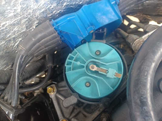
Your photos are clear, so I took one of them and marked it up to
explain that we need to ensure that the rotor tip (installed/bolted
to the distributor shaft) needs to be directly above. Check this
out:
You must be registered for see images attach
If you pull the distributor and the rotor tip is 180 degrees out from the marks in
this photo, then you have located your problem. Get out the pin punch, knock
this pin out, spin the shaft 180 degrees, put it all back together, reinstall the dizzy,
and you should have no problem hitting the CMP <> CKP 0 +/-2 degrees setting.
And if you happen to take a photo of the entire dizzy when it's wrong vs. when you
get it right, then posting those will be a Rosetta Stone of sorts for so many Vortec owners
that are having issues in this area. :0)
Let us know what you discover.
Cheers --
Last edited:
...the prevailing theory is that a twelve-year-old in China makes the gear and pops the dimple into it, and is putting the dimple 180 degrees out. Correctly, the dimple and the roll-pin holes line up with the valley between gear teeth. Incorrectly, the dimple and roll pin holes line up with the flat-topped peak of a gear tooth.
Getting the gear teeth right means putting the dimple wrong...but if the distributor adjusts properly, no harm no foul, and nobody can tell once it's put together.
Getting the gear teeth right means putting the dimple wrong...but if the distributor adjusts properly, no harm no foul, and nobody can tell once it's put together.
Awesome, thank you for the tip. I'll pull the distributor and take some pics. I never would of guest that because before I removed the intake it was at -1. Now that I reinstalled the intake it won't let me get back to at least that.Greetings @SUBURBAN5,
Your too far positive, change one tooth, then too far negative with
insufficient overlap to get to the zero setting does sound like the phasing
issue between the 13-tooth gear vs the distributor shaft that it's pinned to.
Your photos are clear, so I took one of them and marked it up to
explain that we need to ensure that the rotor tip (installed/bolted
to the distributor shaft) needs to be directly above. Check this
out:
You must be registered for see images attach
If you pull the distributor and the rotor tip is 180 degrees out from the marks in
this photo, then you have located your problem. Get out the pin punch, knock
this pin out, spin the shaft 180 degrees, put it all back together, reinstall the dizzy,
and you should have no problem hitting the CMP <> CKP 0 +/-2 degrees setting.
And if you happen to take a photo of the entire dizzy when it's wrong vs. when you
get it right, then posting those will be a Rosetta Stone of sorts for so many Vortec owners
that are having issues in this area. :0)
Let us know what you discover.
Cheers --
Awesome, thank you for the tip. I'll pull the distributor and take some pics.
I never would of guest that because before I removed the intake it was at -1. Now that I reinstalled the intake it won't let me get back to at least that.
Ahh, that's either new data or I missed this while previously reading your thread?
By the way, did you happen to place an index mark across the distributor base and the intake manifold
before you removed it? A "-1 reading" would be within spec, so if through a mark you made (or a
witness mark from being in service) if we could somehow get the dizzy back to that exact clocking
this might get us out of the woods? And if for some reason we can't achieve that old clocking, why not?
What has changed between now and then?
****
When I wrote my reply last night I contemplated what IF your photos came back and the rotor
firing tip already *is* directly above the roll pin side where it is lined up with the valley between
the 2 teeth? I was going to go into all that, but the probability that the 'too positive in one position,
then 1 tooth over and now too negative' phasing error being the correct answer seemed high enough
that I asked myself why muddy up the story with the low probability 'correct mechanical phasing but
some internal cam sensor malfunction or some other signal integrity' exotica?
****
(Optional Reading if the photos do happen to show the simple 180 degree mechanical phasing error.)
EDIT: Many edits after I initially wrote this. The following may have changed if you read it before
~ noon (Eastern) on 24-Feb-2024.
But just in case you reply back with a clear photo showing the rotor firing tip already is directly
over the roll pin where it's lined up to the valley between 2 teeth, then we haven't hit a brick
wall, troubleshooting-wise. Instead, here's the garden path that we will end up wandering
down:
we have to figure out how the CMP (CaM Position) sensor is either:
* Sending the ECM an uncalibrated/misleading/distorted position signal? Or is it generating a
good signal, but Mr. Wiring Harness is making a noisy/jittery mess of it* while on it's way up to the ECM?
* Or (even lower probability) the ECM is getting a valid/calibrated cam position signal and yet is
managing to misinterpret it? (Mis-measuring time of signal arrival vs. the master reference
{CKP} prior to A/D conversion?) Or obscure coding error only, buried deep, and affecting only
this 'Cam Retard' PID fixed 3 software revisions ago...but we are so in the weeds that nobody
ever noticed...and this firmware fix change never made it up to the level of troubleshooting
conversations on the interwebs?
* Or the ECM/engine are actually cool & copacetic with each other, but the problem is over in the zip code
where your ECM and your specific scan device aren't communicating about this value properly?
* Is there any kind of unusual RFI source in your vehicle or workspace? (Think huge Class D switching
audio amps, or you just happen to live right next to a 50KW radio station transmitter, etc.) In English,
did you happen to also install a skull-crushing audio system 'while you were at it'. :0)
* Step #1: Do we have a ground between the ECU and the engine that somehow got disturbed
in all the engine bay activity, is now either marginal or bad, and instead of a clean signal between
the CMP, CKP, and the ECU, it's got enough hash superimposed on top that the computer is being
confused/misled during the A/D conversion or timing calculation? (Yes, I put this out of sequence
on purpose, just to emphasize that when weirdness is observed in a mechanical/analog/digital closed
loop system, good grounding is essential, and must be the first thing we reverify. (Especially if the
parts cannon is in the batter's box warming up and threatening to visit some Humpty Dumpty
onto Mr. Piggy Bank?)
* Step #2: Are you using the aftermarket 'set and forget' can't adjust distributor hold down
fork? Or are you using the factory distributor hold down clamp that allows you to clock the
dizzy in order to make this adjustment? (Whoever came up with the aftermarket thingy
simply didn't understand the big picture?) Yes, I put this out of sequence also. The point I'm
trying to make is that we always need to prove all the basic stuff is right before we chase after
the exotic stuff. (!)
* Speaking of which, how is your CranK Position sensor doing? Too far away giving weak/marginal signal,
too close and rubbing, etc? Remember this CMP <> CKP synchronization check is done by the
ECU, and a goofy/marginal CKP sensor might be just good enough for the engine to operate,
but at the same time some signal artifact is now throwing off the 'Cam Retard' check?
* I happened to look at the thickness of the teeth on the distributor gear, and they look fine.
So at least we can set aside the 'knife-edge' teeth slop for the moment.
* Are you using the same piece of test equipment now that you were using when you got that
desirable "-1 degree" reading? If not, was the original piece of test equipment more or less
accurate than the one that you are using now?
If it's the same piece of test equipment, then was it dropped, lent out to a buddy, firmware upgraded,
software upgrade expire, or any other change to it that might make it now report this measurement differently?
(NOTE: A goofy piece of test gear leading a troubleshooter down the garden path is not unheard of.
What is usually learned from this is that it takes a L O N G time to fix something that isn't broken.
Usually followed by smashing a large ball peen hammer into the lying test box like the ape with the bone
in the movie 2001:ASO. :0)
There's always an answer, from a simple corroded signal or ground wire broken off at a pin to
something a bit more exotic. All we have to do is figure out exactly what changed and correct that.
The concept is simple...just gotta chase down a few details and make it so.
")
****
Reading through the above, I have no doubt that you and I are both rooting for a simple mechanical 180 degree out
phasing error for the answer. But if not, troubleshooting plan B is on the back burner simmering away, just
in case. :0) NOTE: If we were neighbors and I had my o-scope in your engine bay I could prove/dispove all the
exotic signal integrity stuff in a few minutes. (I'm an old school scope dope. Don't trust anything in electronics
that I can't see/enjoy firsthand. :0)
But we're doing this remotely. So sometimes when we broach the subject of troubleshooting at/above the level
of a normal dealership service bay or neighborhood garage it feels like I'm trying to take you on a tour of the
Sistine Chapel using only the written word. (Sistine Chapel)
Not only does it take a lot of words, but at the same time it takes just as much effort for you on the receiving end
to pick up what I'm putting down. (And if I get this wrong, smellin' what I stepped in. :0)
Sending the simplest possible scenario vibes your way.
Cheers --
Attachments

Last edited:
Wow that was quit a bit of info. Took a few times but I think I got it. So here's the latest. YES same scanner as day 1 and same oem parts. Only thing changed was the upper intake removed and installed for a lifter inspection/adjustment.Ahh, that's either new data or I missed this while previously reading your thread?
By the way, did you happen to place an index mark across the distributor base and the intake manifold
before you removed it? A "-1 reading" would be within spec, so if through a mark you made (or a
witness mark from being in service) if we could somehow get the dizzy back to that exact clocking
this might get us out of the woods? And if for some reason we can't achieve that old clocking, why not?
What has changed between now and then?
****
When I wrote my reply last night I contemplated what IF your photos came back and the rotor
firing tip already *is* directly above the roll pin side where it is lined up with the valley between
the 2 teeth? I was going to go into all that, but the probability that the 'too positive in one position,
then 1 tooth over and now too negative' phasing error being the correct answer seemed high enough
that I asked myself why muddy up the story with the low probability 'correct mechanical phasing but
some internal cam sensor malfunction or some other signal integrity' exotica?
****
(Optional Reading if the photos do happen to show the simple 180 degree mechanical phasing error.)
EDIT: Many edits after I initially wrote this. The following may have changed if you read it before
~ noon (Eastern) on 24-Feb-2024.
But just in case you reply back with a clear photo showing the rotor firing tip already is directly
over the roll pin where it's lined up to the valley between 2 teeth, then we haven't hit a brick
wall, troubleshooting-wise. Instead, here's the garden path that we will end up wandering
down:
we have to figure out how the CMP (CaM Position) sensor is either:
* Sending the ECM an uncalibrated/misleading/distorted position signal? Or is it generating a
good signal, but Mr. Wiring Harness is making a noisy/jittery mess of it* while on it's way up to the ECM?
* Or (even lower probability) the ECM is getting a valid/calibrated cam position signal and yet is
managing to misinterpret it? (Mis-measuring time of signal arrival vs. the master reference
{CKP} prior to A/D conversion?) Or obscure coding error only, buried deep, and affecting only
this 'Cam Retard' PID fixed 3 software revisions ago...but we are so in the weeds that nobody
ever noticed...and this firmware fix change never made it up to the level of troubleshooting
conversations on the interwebs?
* Or the ECM/engine are actually cool & copacetic with each other, but the problem is over in the zip code
where your ECM and your specific scan device aren't communicating about this value properly?
* Is there any kind of unusual RFI source in your vehicle or workspace? (Think huge Class D switching
audio amps, or you just happen to live right next to a 50KW radio station transmitter, etc.) In English,
did you happen to also install a skull-crushing audio system 'while you were at it'. :0)
* Step #1: Do we have a ground between the ECU and the engine that somehow got disturbed
in all the engine bay activity, is now either marginal or bad, and instead of a clean signal between
the CMP, CKP, and the ECU, it's got enough hash superimposed on top that the computer is being
confused/misled during the A/D conversion or timing calculation? (Yes, I put this out of sequence
on purpose, just to emphasize that when weirdness is observed in a mechanical/analog/digital closed
loop system, good grounding is essential, and must be the first thing we reverify. (Especially if the
parts cannon is in the batter's box warming up and threatening to visit some Humpty Dumpty
onto Mr. Piggy Bank?)
* Step #2: Are you using the aftermarket 'set and forget' can't adjust distributor hold down
fork? Or are you using the factory distributor hold down clamp that allows you to clock the
dizzy in order to make this adjustment? (Whoever came up with the aftermarket thingy
simply didn't understand the big picture?) Yes, I put this out of sequence also. The point I'm
trying to make is that we always need to prove all the basic stuff is right before we chase after
the exotic stuff. (!)
* Speaking of which, how is your CranK Position sensor doing? Too far away giving weak/marginal signal,
too close and rubbing, etc? Remember this CMP <> CKP synchronization check is done by the
ECU, and a goofy/marginal CKP sensor might be just good enough for the engine to operate,
but at the same time some signal artifact is now throwing off the 'Cam Retard' check?
* I happened to look at the thickness of the teeth on the distributor gear, and they look fine.
So at least we can set aside the 'knife-edge' teeth slop for the moment.
* Are you using the same piece of test equipment now that you were using when you got that
desirable "-1 degree" reading? If not, was the original piece of test equipment more or less
accurate than the one that you are using now?
If it's the same piece of test equipment, then was it dropped, lent out to a buddy, firmware upgraded,
software upgrade expire, or any other change to it that might make it now report this measurement differently?
(NOTE: A goofy piece of test gear leading a troubleshooter down the garden path is not unheard of.
What is usually learned from this is that it takes a L O N G time to fix something that isn't broken.
Usually followed by smashing a large ball peen hammer into the lying test box like the ape with the bone
in the movie 2001:ASO. :0)
There's always an answer, from a simple corroded signal or ground wire broken off at a pin to
something a bit more exotic. All we have to do is figure out exactly what changed and correct that.
The concept is simple...just gotta chase down a few details and make it so.
****
Reading through the above, I have no doubt that you and I are both rooting for a simple mechanical 180 degree out
phasing error for the answer. But if not, troubleshooting plan B is on the back burner simmering away, just
in case. :0) NOTE: If we were neighbors and I had my o-scope in your engine bay I could prove/dispove all the
exotic signal integrity stuff in a few minutes. (I'm an old school scope dope. Don't trust anything in electronics
that I can't see/enjoy firsthand. :0)
But we're doing this remotely. So sometimes when we broach the subject of troubleshooting at/above the normal
dealership service bay or neighborhood garage it feels like I'm trying to take you on a tour of the Sistine Chapel
using only the written word. (Sistine Chapel)
Not only does it take a lot of words, but at the same time it takes just as much effort for you on the receiving end
to pick up what I'm putting down. (And if I get this wrong, smellin' what I stepped in. :0)
Sending the simplest possible scenario vibes your way.
Cheers --
Truck was at the shop because it wasn't running nor idling when I got done. Family member with a automotive shop took in the truck and found it was a faulty map sensor. Upon testing and retracing My steps they looked and tested all over the engine. Meaning valves,rods, pistons, compression and electrical signal. He and another veteran mechanic checked signal from cam and crank using some fancy machine that checks wave length. According to them everything checked out.
When they removed the distributor they lined up the pins and inspected the position of the rotor.
Fast forward a few days best they could do was -7. They used a different bidirectional scanner but got the same reading as my original scanner.
There conclusion is the timing chain could be stretched.
Now in my case. No I did not mark before and after the distributor was removed. Just like the -1 degree was from a few months ago.
But I figured a timing chain shouldn't stretch between 4 or so months of regular driving and not towing...
Yes I do like to speed but even then we're talking what 5 degrees to get it to spec?
My plan. Change out the distributor gear for ***** and giggles, check ground at the rear head grounds since that's next to the distributor. Last this truck does not have any electrical upgrades besides the big 3. No goofy sound systems or tvs/cameras/cb radio.
Wow that was quit a bit of info. Took a few times but I think I got it. So here's the latest. YES same scanner as day 1 and same oem parts. Only thing changed was the upper intake removed and installed for a lifter inspection/adjustment.
Truck was at the shop because it wasn't running nor idling when I got done. Family member with a automotive shop took in the truck and found it was a faulty map sensor. Upon testing and retracing My steps they looked and tested all over the engine. Meaning valves,rods, pistons, compression and electrical signal. He and another veteran mechanic checked signal from cam and crank using some fancy machine that checks wave length. According to them everything checked out.
When they removed the distributor they lined up the pins and inspected the position of the rotor.
Fast forward a few days best they could do was -7. They used a different bidirectional scanner but got the same reading as my original scanner.
There conclusion is the timing chain could be stretched.
Now in my case. No I did not mark before and after the distributor was removed. Just like the -1 degree was from a few months ago.
But I figured a timing chain shouldn't stretch between 4 or so months of regular driving and not towing...
Yes I do like to speed but even then we're talking what 5 degrees to get it to spec?
My plan. Change out the distributor gear for ***** and giggles, check ground at the rear head grounds since that's next to the distributor. Last this truck does not have any electrical upgrades besides the big 3. No goofy sound systems or tvs/cameras/cb radio.
Alright, thanks for the detailed status report. I've got a better feel for how friendly/hostile
your engine bay is. Actually sounds like a lot of troubleshooting variables have been covered by
your posse.
Re: the distributor timing gear. The key to my desire to swap that dizzy gear 180 degrees from it's
current setting is because you are currently straddled +7 and then -7. (Assuming each time that you
are also twisting the housing as far as it will go until you hit a physical restriction impeding further
adjustment towards the goal.)
IF that's the case, then when you swap the gear you are going to change the phasing 1/2 of a gear tooth.
(360 degrees / 13 teeth = ~28 degrees per tooth.) So for the sake of argument, you are going to shift the
mechanical phasing ~14 degrees. And before where 1 position was -7 off, while 1 tooth over was +7 off,
now one tooth will allow you to hit the 0 degree goal within the limited dizzy swing space available, while
that 1 tooth off position you previously tried will now be at least 21 degrees off.
Does this make sense?
Also, I do believe that timing chains do indeed stretch, and when this happens the CMP
sensor inside the distributor out back falls behind the CKP sensor up front to equal the amount of
stretch that's occurred. But if this were to happen, I would expect your 2 dizzy tooth choices would be
late/way too late, vs a little late vs a little early like you currently have?
****
The bottom line is that all the old distributor-savvy dudes are hanging up their spurs or have already
left the building so to speak. And most of them had all the room in the world to swing their dizzys
to get whatever base timing they wanted. And they viewed a dizzy (correctly) as the *source* of
their ignition timing. (Pre-computer HEI = base timing + centrifugal advance + vacuum advance).
TBI? (Dizzy position sets base timing, computer adds additional advance based on rpm + load + engine coolant
temp + knock sensor feedback, blah blah blah. :0)
****
Meanwhile, here we are living in Vortec land, and the CKP sensor is the *source* of our base timing. Period.
And then there's some tables full of 1s and 0s for the computer (and in turn represented in
hexadecimal {or even translated a further iteration into degrees of crank rotation for human
consumption}) where the timing advance curves for rpm and load are obtained that the computer
indexes into after reading ALL the sensor inputs and performing some high speed gonkulation.
(Sorry about that, that's a dense paragraph that I can't seem to make better.)
And finally, after the ECU(VCM) > ICM > Coil > cap center wire > Rotor success chain has been
navigated, all we are trying to do with this 'cam retard' adjustment is make sure that the closest
distributor terminal to the rotor tip at the time of spark generation/delivery is also the correct
spark plug wire terminal. (aka: Plain & simple physical dizzy clocking to maximize misfire avoidance. (!)
Complicating matters in 2024 is that this is not how most of the dwindling dizzy dudes think
about the dizzy. And then when I look in the back of the engine bay and see how tight everything
is? It's one of the few times where I miss the brand F design where the dizzy is up front.
Again, I concur with your plan of attack. Pictures please. And if for some unknown reason the
re-phased 13 tooth gear makes the issue even worse? (insert head scratching here) Then I
would reserve the right to put it back to the way it is right now, but choose the lesser evil of
putting it +7 degrees ahead. Why? Part of the answer is that theoretical timing chain wear
plus the fact that we spend way more time with our timing advanced to 24-30+ degrees BTDC,
versus any time ATDC. Just trying to keep the correct terminal the closest to the rotor firing
tip as much as possible.
Whew -- Who knew that getting the spark from coil to plug was so complicated? :0)
Good on you for maintaining a can-do attitude through all this. It's sad to see elsewhere where
others get so frustrated they just pull the plug and part out the old gal...
Cheers --
Last edited:
Ok so I understand you correctly. Your saying when I install the new 13teeth distributor gear install it exactly like the current one is? Reason why I ask is because if I install it any other way I would be 180 out right? Also this is to be done at TDC piston 1 like GM states right?Alright, thanks for the detailed status report. I've got a better feel for how friendly/hostile
your engine bay is. Actually sounds like a lot of troubleshooting variables have been covered by
your posse.
Re: the distributor timing gear. The key to my desire to swap that dizzy gear 180 degrees from it's
current setting is because you are currently straddled +7 and then -7. (Assuming each time that you
are also twisting the housing as far as it will go until you hit a physical restriction impeding further
adjustment towards the goal.)
IF that's the case, then when you swap the gear you are going to change the phasing 1/2 of a gear tooth.
(360 degrees / 13 teeth = ~28 degrees per tooth.) So for the sake of argument, you are going to shift the
mechanical phasing ~14 degrees. And before where 1 position was -7 off, while 1 tooth over was +7 off,
now one tooth will allow you to hit the 0 degree goal within the limited dizzy swing space available, while
that 1 tooth off position you previously tried will now be at least 21 degrees off.
Does this make sense?
Also, I do believe that timing chains do indeed stretch, and when this happens the CMP
sensor inside the distributor out back falls behind the CKP sensor up front to equal the amount of
stretch that's occurred. But if this were to happen, I would expect your 2 dizzy tooth choices would be
late/way too late, vs a little late vs a little early like you currently have?
****
The bottom line is that all the old distributor-savvy dudes are hanging up their spurs or have already
left the building so to speak. And most of them had all the room in the world to swing their dizzys
to get whatever base timing they wanted. And they view a dizzy (correctly) as the *source* of
their ignition timing. (Pre-computer HEI = base timing + centrifugal advance + vacuum advance).
TBI? (Dizzy position sets base timing, computer adds additional advance based on rpm + load + engine coolant
temp + knock sensor feedback, blah blah blah. :0)
****
Meanwhile, here we are living in Vortec land, and the CKP sensor is the *source* of our base timing. Period.
And then there's some tables full of 1s and 0s for the computer (and in turn represented in
hexadecimal {or even translated a further iteration into degrees of crank rotation for human
consumption}) where the timing advance curves for rpm and load are obtained that the computer
indexes into after reading ALL the sensor inputs and performing some high speed gonkulation.
(Sorry about that, that's a dense paragraph that I can't seem to make better.)
And finally, after the ECU(VCM) > ICM > Coil > cap center wire > Rotor success chain has been
navigated, all we are trying to do with this 'cam retard' adjustment is make sure that the closest
distributor terminal to the rotor tip at the time of spark generation/delivery is also the correct
spark plug wire terminal. (aka: Plain & simple misfire avoidance. (!)
This is not how most of the dwindling dizzy dudes think about the dizzy. And then when
I look in the back of the engine bay and see how tight everything is? It's one of the few times
I miss the brand F design where the dizzy is up front.
Again, I concur with your plan of attack. Pictures please. And if for some unknown reason the
re-phased 13 tooth gear makes the issue even worse? (insert head scratching here) Then I
would reserve the right to put it back to the way it is right now, but choose the lesser evil of
putting it +7 degrees ahead. Why? Part of the answer is that theoretical timing chain wear
plus the fact that we spend way more time with our timing advanced to 24-30+ degrees BTDC,
versus any time ATDC. Just trying to keep the correct terminal the closest to the rotor firing
tip as much as possible.
Whew -- Who knew that getting the spark from coil to plug was so complicated? :0)
Good on you for maintaining a can-do attitude through all this. It's sad to see elsewhere where
others get so frustrated they just pull the plug and part out the old gal...
Cheers --
Nevermind I reread your advise. By installing the gear 180 out and installing the distributor correctly to TDC you gain half a tooth since the gear is opposite but correct??
Last edited:
Sir,Ok so I understand you correctly. Your saying when I install the new 13 teeth distributor gear install it exactly like the current one is? Reason why I ask is because if I install it any other way I would be 180 out right? Also this is to be done at TDC piston 1 like GM states right?
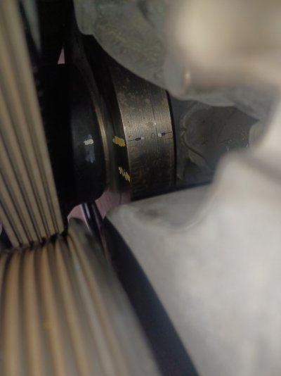
I just looked at your photo again, and I am not offended at all by what I see: (current dizzy gear photo)
If I were in your shoes, I'd depin > swing existing dizzy gear 180 degree > repin ...and see
what happens? And yes, I would definitely get the #1 cylinder on TDC of the compression stroke.
And while you're at it, use a sharpie to mark the dizzy base and the intake manifold with what you
currently have...just because you can. (I like breadcrumbs.)
And if you want to have a brand new gear on hand as a on-shelf spare I don't blame you.
But let's swing that gear and see what you've got? I think that for better or worse, we will
gather valuable info.
Again, thanks for being willing to be the crash test dummy for this Vortec dizzy stuff.
We've got at least one individual recently over this hurdle. It would be very cool to do
it a second time.
Don't forget the photos.

Photos for sure don't worry about that. Hey I appreciate the advice. My pin tool set at work so I was waiting for monday. unless you know the exact size pin I need. All the random shafts I have here are either 1/4 or 1/8 inch. Maybe some nails and screws lolSir,
I just looked at your photo again, and I am not offended at all by what I see: (current dizzy gear photo)
If I were in your shoes, I'd depin > swing existing dizzy gear 180 degree > repin ...and see
what happens? And yes, I would definitely get the #1 cylinder on TDC of the compression stroke.
And while you're at it, use a sharpie to mark the dizzy base and the intake manifold with what you
currently have...just because you can. (I like breadcrumbs.)
And if you want to have a brand new gear on hand as a on-shelf spare I don't blame you.
But let's swing that gear and see what you've got? I think that for better or worse, we will
gather valuable info.
Again, thanks for being willing to be the crash test dummy for this Vortec dizzy stuff.
We've got at least one individual recently over this hurdle. It would be very cool to do
it a second time.
Don't forget the photos.
Similar threads
- Replies
- 4
- Views
- 848
- Replies
- 27
- Views
- 2K
- Replies
- 0
- Views
- 222
Members online
- Orpedcrow
- Willsgirl19
- MarKist
- JPVortex
- HoffmansHaven
- kaqoil
- jus10inbrla
- steeda21
- Drunkcanuk
- Spareparts
- arrg
- Dantheman1540
- lit549
- kenjad96
- AcesOBS2237
- Caman96
- mruvio
- jman2
- Jamest0809
- vallesfj
- yrusohi
- Scooterwrench
- 98BlackSierra
- Diego11
- patrick5050
- TICK
- squirrels2k
- iragsdale
- Goon
- OlSarge
- Devonp87
- Dame Dog
- FighterOfTheFoo
- VIKING_MECHANIC
- Alteca
- Stowburb
- Tomcat71
- shablagoo_gabagool
- bingobobby
- EDNY
- Dravec
- Schurkey
- RAAK
- 95YardArt
- TXStepside
- Aviazx
- Erocksmash
- 99xcss4
- That black gmt
- Will Force
Total: 1,723 (members: 60, guests: 1,663)