
'96+ Vortec Distributors - A visual perspective on the P1345 DTC for misfire troubleshooters (Part 1)
As a troubleshooter, my favorite engine parts are the ones that:
A) Rarely fail.
B) When they do fail, the failure footprint is both unique and intuitive.
C) There is a much better part readily available that can be used to prevent similar failures down the road.
A perfect example of the above would be a stock connecting rod that fails due to being asked to work at
a higher hp & rpm level than it was designed to handle. More failed connecting rods are seen at the dragstrip
in the heat of battle than in an idling car being rolled through a drive-through car wash. It all makes sense.
****
And then there's the Vortec distributor. Applying lessons learned during old school SBC distributor troubleshooting
(ie: what worked from '55-'95) can lead us old-timers down the garden path. And the guys raised on modern stationary
ignition distribution systems (dedicated Coil near Plug / Coil on Plug) find the distribution of sparks via a spinning rotor
to be just this side of trying to get a Jacob's ladder to work under the hood.
(Nice home-brewed Jacob's ladder - the good stuff starts at ~2:08)
Meanwhile, most of the guys that were factory trained on the quirks associated with the Vortec dizzy when it was first
released 28 years ago are either retired or increasingly hard to find in the real world. And given the ever-cheapening
parts in our supply chain, these last-gasp distributors can fail too often, cause a blurry failure footprint that can make
it look/feel like the engine is suffering from a fuel delivery or mechanical sealing issue, and the search is on for a 'better
than OEM' replacement for those of us who prefer our GMT400s on the road, rain or shine.
On top of all this, people with a good track record are reporting that they have driven long periods of time with a P1345 DTC
with no ill effects. On the other hand, different people are experiencing significant intermittent misfires that go away with
clearing a P1345 DTC. The more I studied the P1345 issue, it seemed that if achieving the factory specified setting wasn't
possible (more on this later) ...an error in one direction made a much bigger difference than an error in the opposing direction?
What does this mean?
****
Given that the majority of troubleshooter types are Visual Learners, I am hoping that the following illustration will
help to snap everything into sharper focus:
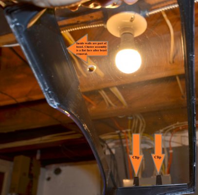
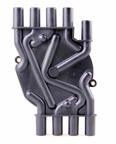
(Inverted cap view. Actual rotor rotation is Clockwise from the mechanic in engine bay bird's-eye view. See 1st attachment for normal cap view.)
Here's a list of things to ponder as a troubleshooter while looking at the picture above:
* As discussed elsewhere in the forum, on Vortec engines the base timing comes from the CKP
(CranK Position) sensor, NOT from the physical twisting of the distributor housing as expected by those of
us who were raised on conventional distributors. (Whether mechanical points, HEI large or TBI small cap.)
In English, just because the timing is correct does *not* mean that the rotor is correctly lined up with the
spark plug wire terminals. This is why there is the CMP vs CKP sync check. Some scan tools will refer to
this as "CMP Ret". (CaM Position Retard.)
* When you look at the cap remember that because we're dealing with 4-stroke engines, the crank spins
720° for the cam (and distributor) to rotate 360°. But since everything is referenced off of the crank position,
the best that I can figure out is that when the 'CMP Ret' is reported to be 20°, this means that the distributor is
physically off 10°.
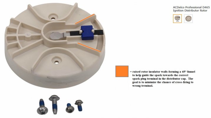
* As we know, there is 90° of crank rotation between each cylinder firing. And because of the 2:1 ratio of cam to crank
timing gears, there is a corresponding 45° distributor rotation from 1 spark plug terminal to the next. Looking at
the 45° orange pie slice that I drew, you can see that the spark plug terminal has (physically) 22.5° before and after
it set aside for the constantly varying timing spark to occur. If you look at the spark timing light blue arc that I drew
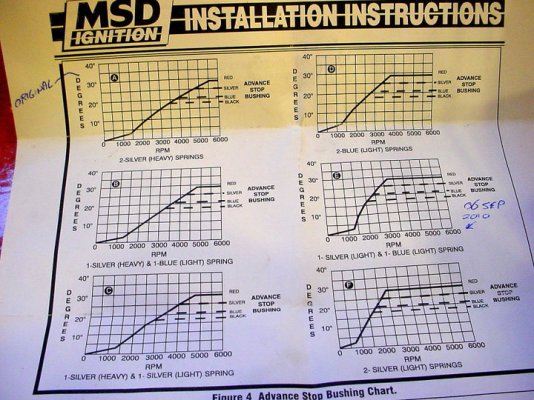
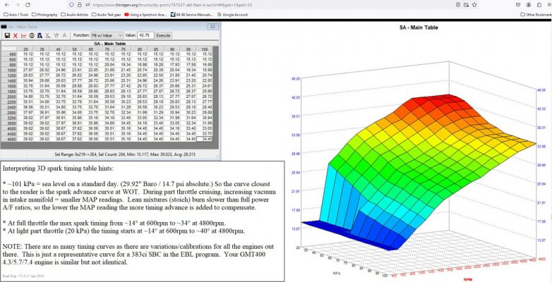
(marked up in crankshaft degrees) this is where the spark will occur IF the 'CMP RET' is set to 0°. (Refer to 3D timing
map in the 3rd attachment.) But if you look through the forum you will see plenty of discussions where the CMP RET
is off by a full tooth (~27.7°) or more. (!)
If you take that blue arc and move it from the correct position to + or - 28° (simulating a mis-stabbed dizzy) then you
can start to see how this distributor housing phasing error can cause misfires to adjacent cylinders when either near
the base timing -or- near max timing. It does make a difference!
* Let's say that we're supposed to be firing the #8 cylinder at the top of the photo. Let's say that the distributor
is off so that the rotor is closer to the #1 distributor cap terminal. Since the #1 cylinder is already 90 degrees after
#8 in the firing order, IF the spark were to go to #1 there's no long term harm done, for that spark plug is firing into
a cylinder that's already burned it's charge. (But at the same time the #8 misfire will still be felt.)
On the other hand, let's say that the distributor is off in the other direction far enough that the #4 spark plug terminal
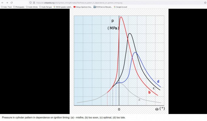
is the closest. So instead of firing #8 at the correct time we end up firing the #4 cylinder early. In this case, we are
setting up a situation where we could be causing detonation from a too-early firing, the pressure builds up too soon,
and is trying to force the #4 cylinder back down the bore. (And if #4 lights off early + the missing power stroke in #8,
this could cause a much more noticeable knock in #4 + misfire in #8 combo.)
* But given that normal spark timing is anywhere from TDC to ~40° BTDC it's easier to set up a crossfire on the
already burning cylinder *before* in the firing order than it is to cause a crossfire with the spark plug terminal that's
*after* the correct cylinder in the firing order. And since the 13 teeth on the distributor gear divided into 360° = ~27.7°
per gear tooth, then as you can see it's possible to stab the distributor in such a way where these before or after
adjacent cylinder misfires are possible.
NOTE: Instead of all or nothing, due to the fact that the ignition timing is constantly moving, if the distributor is set
somewhat off but the engine still runs, then there's the high probability that the correct cylinder terminal will be the
closest during the 'mid-range' values of the spark map. But at one extreme, the misfires will be more pronounced
where the most timing is rolled in by the computer.
On the other end of the mistimed continuum, the vehicle is super rough at/near base timing, but actually clears up a
bit when the computer adds more timing and suddenly now the correct terminal is closest? With careful observation
from the driver's seat, instead of "it's intermittently running rough" careful analysis of the symptoms (only down low vs
only up high) will help us predict how much and which direction the distributor housing phasing error is. (!)
And that IF this distributor position error causes the symptom to present when the timing is near max advance, a lightly
loaded GMT400 with a driver driving a stick (who favors a lot of rpm) may report running into high rpm misfiring under
light load. Meanwhile, a different driver can load up that same vehicle, get in, drive in a lower rpm band, and thanks to
the combo of lower rpm and heavy load, not experience the misfire that the first driver felt? (Think dad & lad scenario
-- old salt vs hot shoe. :0) It's possible. And the reverse is true, all depending upon which direction the distributor
housing phasing error is in relationship to the camshaft/crankshaft.
****
I was going to discuss buying a replacement dizzy with the 13 tooth distributor gear installed 180° out, and how this
leads to a situation where 1 tooth is too far off in one direction, while the next tooth is off too far in the other direction,
but I'm not sure that anyone is still reading this...and frankly I am tired of typing & thinking. :0)
But I've been trying to figure out how @L31MaxExpress and @Schurkey could both report driving on P1345 DTCs
long term with no driveability issues, and thanks to a little basic geometry under the distributor cap while admiring that
3D spark table map, I can now see how this could occur. But for the vast majority of Vortec-powered GMT400 owners
reading this, it's best to set the CMP RET to the factory specs, and deal with one less troubleshooting variable, if for no
other reason than to allow the Black Box to more accurately diagnose misfires on your behalf.
Hope this helps someone out there. Whether it's the old guys who can remember setting their points gap on the side of
the road using a matchbook cover, or possibly the newer enthusiasts who are used to working on ignitions with no
moving parts involved between the VCM and the spark plug.
Cheers --
As a troubleshooter, my favorite engine parts are the ones that:
A) Rarely fail.
B) When they do fail, the failure footprint is both unique and intuitive.
C) There is a much better part readily available that can be used to prevent similar failures down the road.
A perfect example of the above would be a stock connecting rod that fails due to being asked to work at
a higher hp & rpm level than it was designed to handle. More failed connecting rods are seen at the dragstrip
in the heat of battle than in an idling car being rolled through a drive-through car wash. It all makes sense.
****
And then there's the Vortec distributor. Applying lessons learned during old school SBC distributor troubleshooting
(ie: what worked from '55-'95) can lead us old-timers down the garden path. And the guys raised on modern stationary
ignition distribution systems (dedicated Coil near Plug / Coil on Plug) find the distribution of sparks via a spinning rotor
to be just this side of trying to get a Jacob's ladder to work under the hood.
(Nice home-brewed Jacob's ladder - the good stuff starts at ~2:08)
Meanwhile, most of the guys that were factory trained on the quirks associated with the Vortec dizzy when it was first
released 28 years ago are either retired or increasingly hard to find in the real world. And given the ever-cheapening
parts in our supply chain, these last-gasp distributors can fail too often, cause a blurry failure footprint that can make
it look/feel like the engine is suffering from a fuel delivery or mechanical sealing issue, and the search is on for a 'better
than OEM' replacement for those of us who prefer our GMT400s on the road, rain or shine.
On top of all this, people with a good track record are reporting that they have driven long periods of time with a P1345 DTC
with no ill effects. On the other hand, different people are experiencing significant intermittent misfires that go away with
clearing a P1345 DTC. The more I studied the P1345 issue, it seemed that if achieving the factory specified setting wasn't
possible (more on this later) ...an error in one direction made a much bigger difference than an error in the opposing direction?
What does this mean?
****
Given that the majority of troubleshooter types are Visual Learners, I am hoping that the following illustration will
help to snap everything into sharper focus:
You must be registered for see images attach
(Inverted cap view. Actual rotor rotation is Clockwise from the mechanic in engine bay bird's-eye view. See 1st attachment for normal cap view.)
Here's a list of things to ponder as a troubleshooter while looking at the picture above:
* As discussed elsewhere in the forum, on Vortec engines the base timing comes from the CKP
(CranK Position) sensor, NOT from the physical twisting of the distributor housing as expected by those of
us who were raised on conventional distributors. (Whether mechanical points, HEI large or TBI small cap.)
In English, just because the timing is correct does *not* mean that the rotor is correctly lined up with the
spark plug wire terminals. This is why there is the CMP vs CKP sync check. Some scan tools will refer to
this as "CMP Ret". (CaM Position Retard.)
* When you look at the cap remember that because we're dealing with 4-stroke engines, the crank spins
720° for the cam (and distributor) to rotate 360°. But since everything is referenced off of the crank position,
the best that I can figure out is that when the 'CMP Ret' is reported to be 20°, this means that the distributor is
physically off 10°.
* As we know, there is 90° of crank rotation between each cylinder firing. And because of the 2:1 ratio of cam to crank
timing gears, there is a corresponding 45° distributor rotation from 1 spark plug terminal to the next. Looking at
the 45° orange pie slice that I drew, you can see that the spark plug terminal has (physically) 22.5° before and after
it set aside for the constantly varying timing spark to occur. If you look at the spark timing light blue arc that I drew
(marked up in crankshaft degrees) this is where the spark will occur IF the 'CMP RET' is set to 0°. (Refer to 3D timing
map in the 3rd attachment.) But if you look through the forum you will see plenty of discussions where the CMP RET
is off by a full tooth (~27.7°) or more. (!)
If you take that blue arc and move it from the correct position to + or - 28° (simulating a mis-stabbed dizzy) then you
can start to see how this distributor housing phasing error can cause misfires to adjacent cylinders when either near
the base timing -or- near max timing. It does make a difference!
* Let's say that we're supposed to be firing the #8 cylinder at the top of the photo. Let's say that the distributor
is off so that the rotor is closer to the #1 distributor cap terminal. Since the #1 cylinder is already 90 degrees after
#8 in the firing order, IF the spark were to go to #1 there's no long term harm done, for that spark plug is firing into
a cylinder that's already burned it's charge. (But at the same time the #8 misfire will still be felt.)
On the other hand, let's say that the distributor is off in the other direction far enough that the #4 spark plug terminal
is the closest. So instead of firing #8 at the correct time we end up firing the #4 cylinder early. In this case, we are
setting up a situation where we could be causing detonation from a too-early firing, the pressure builds up too soon,
and is trying to force the #4 cylinder back down the bore. (And if #4 lights off early + the missing power stroke in #8,
this could cause a much more noticeable knock in #4 + misfire in #8 combo.)
* But given that normal spark timing is anywhere from TDC to ~40° BTDC it's easier to set up a crossfire on the
already burning cylinder *before* in the firing order than it is to cause a crossfire with the spark plug terminal that's
*after* the correct cylinder in the firing order. And since the 13 teeth on the distributor gear divided into 360° = ~27.7°
per gear tooth, then as you can see it's possible to stab the distributor in such a way where these before or after
adjacent cylinder misfires are possible.
NOTE: Instead of all or nothing, due to the fact that the ignition timing is constantly moving, if the distributor is set
somewhat off but the engine still runs, then there's the high probability that the correct cylinder terminal will be the
closest during the 'mid-range' values of the spark map. But at one extreme, the misfires will be more pronounced
where the most timing is rolled in by the computer.
On the other end of the mistimed continuum, the vehicle is super rough at/near base timing, but actually clears up a
bit when the computer adds more timing and suddenly now the correct terminal is closest? With careful observation
from the driver's seat, instead of "it's intermittently running rough" careful analysis of the symptoms (only down low vs
only up high) will help us predict how much and which direction the distributor housing phasing error is. (!)
And that IF this distributor position error causes the symptom to present when the timing is near max advance, a lightly
loaded GMT400 with a driver driving a stick (who favors a lot of rpm) may report running into high rpm misfiring under
light load. Meanwhile, a different driver can load up that same vehicle, get in, drive in a lower rpm band, and thanks to
the combo of lower rpm and heavy load, not experience the misfire that the first driver felt? (Think dad & lad scenario
-- old salt vs hot shoe. :0) It's possible. And the reverse is true, all depending upon which direction the distributor
housing phasing error is in relationship to the camshaft/crankshaft.
****
I was going to discuss buying a replacement dizzy with the 13 tooth distributor gear installed 180° out, and how this
leads to a situation where 1 tooth is too far off in one direction, while the next tooth is off too far in the other direction,
but I'm not sure that anyone is still reading this...and frankly I am tired of typing & thinking. :0)
But I've been trying to figure out how @L31MaxExpress and @Schurkey could both report driving on P1345 DTCs
long term with no driveability issues, and thanks to a little basic geometry under the distributor cap while admiring that
3D spark table map, I can now see how this could occur. But for the vast majority of Vortec-powered GMT400 owners
reading this, it's best to set the CMP RET to the factory specs, and deal with one less troubleshooting variable, if for no
other reason than to allow the Black Box to more accurately diagnose misfires on your behalf.
Hope this helps someone out there. Whether it's the old guys who can remember setting their points gap on the side of
the road using a matchbook cover, or possibly the newer enthusiasts who are used to working on ignitions with no
moving parts involved between the VCM and the spark plug.
Cheers --
Attachments
-
 vortec distributor cap bird's eye view.jpg101.7 KB · Views: 28
 -
 Delco Vortec Rotor 45 degree spark funnel.jpg115.5 KB · Views: 29
 -
 383 SBC Spark Timing 3D chart with hints (EBL Flash II SA Help needed - Third Generation F-Bod...jpg260.8 KB · Views: 29
 -
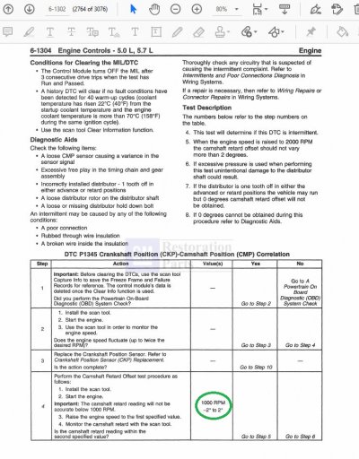 P1345 CMP CKP sync specs (circled) -- 99 Chevrolet & GMC CK Truck SM - Vol. 1 & 2.jpg238.2 KB · Views: 30
Last edited: