Hello JPVortex,
I checked the '94 FSM wiring diagrams for the TBI setup, and there are actually *
3* physically separate communication paths between the '94 PCU (ECU)
and the troubleshooter in the interior. 1 for the SES light, and *2* in the ALDL connector.
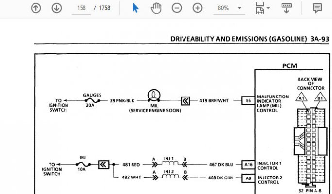
* The first is a dedicated circuit (#419) so that the computer can illuminate the SES light for the human. (This works, so not our current focus, see attachment #1)
* The second is a circuit, that when grounded during KOEO tells the computer to flash numeric codes to the 'I gots no scan tool ' human in order to
communicate the failing test #, otherwise default to constant flashing 12s. Most of us know this circuit by the time honored paper clipping of pin A
(ground circuit #450) to pin B (circuit #451), which eventually leads us back to the PCM's "Diagnostic Test" pin A14.
* Guess what? When the 'I gots no scan tool' human decides to call in reinforcements, the mechanic with the scan tool/magic brick is going to connect to
the same special 12-pin OBD1 connector, and *this* is where the 3rd communication path finally gets involved. That's right, for those of you who
cheated and looked ahead at p. 3A-79 below (p. 144 in the .pdf file) ...pin
M is connected via circuit #1061 to pin
F9 on the PCU. If I'm not mistaken
(and I'm on thin ice) inside the computer there's gonna be a UART (Universal Asynchronous Receiver Transmitter) that's going to handshake with the
mechanic's brick, and then via "Serial Data" the 2 electronic entities will establish communication between each other, and now the scan tool can be used
to dig a lot deeper into what's up.
You must be registered for see images attach
Given this physical wiring layout, it's quite possible to have no steady SES light ever, or a steady SES light
but no flashing codes available...but the mechanic's brick works just fine?
And getting that light to work may involve tracing the power from the ignition switch to the 'GAUGES'
fuse, through the light itself, and finally the ability for the PCM pin E6 to supply a ground in order to
cause current flow through the SES lamp. So that will get you the illuminated SES warning light.
But IF you can get the steady on SES light, but can't retrieve the codes, then now we're all about
verifying the wiring to pin B at the ALDL connector.
But if we are getting full SES light functionality, both warning, error codes, and Field Service functions,
but we *can't* get the scan tool to connect, then at this point all I care about is the integrity of the connection
between pin
M on the ALDL connector and pin
F9 on the PCM. (ECU)
****
By the way, I share all of the above from fixing 'no worky' yet known-good avionics test equipment that
kept us from working on the actual writeup. I'm sincerely hoping to come back to this thread and read
that you've found the break in the serial data communication path and that the scan tool is doing the
chitter chatter with your PCM. (Assuming that the treasure yard PCM acts the same way, making the
probability that the PCM is the victim of a bad wire and not the actual perpetrator of the whole
incommunicado thing.)
And if the replacement PCM fixes everything, it was still good practice for yours truly to wade around in the OBD1 TBI
wiring diagrams that document the ALDL<>PCM area.
:0)
Give everything between the ALDL connector and your PCM some careful scrutiny & let us know what you find.
Best of luck with the hunt. We gotta get your GMT400 back on the road, especially since you had the good taste
to upgrade the manual tranny in it. :0)
Cheers --


")