Ok so i was initially not performing the leakdown correctly i was under the impression that you apply x amount of air and watch it hold without a constant air source. So that being said i repeated the process correctly and at 100 psi inlet side cylinder pressures were all at 90 psi or 88. Air was observed slightly at crank exhaust and throttle body not sure what too make of it.
Thanks for coming back with that status report on your test procedure.
Note: Just about everyone reading this has hit similar snags while familiarizing
ourselves with getting accurate results from compression and leakdown tests. Good
on you for figuring out how the sideways data was generated -- that's how we
all gain the experience we need to proceed down the path towards the goal of
truly successful DIY. :0)
****
Alright, I decided to stop and reread the entire thread. (In a subsequent reply
I will summarize all that you've tried so far in order for everyone to have a
consistent troubleshooting perspective.)
In order to make troubleshooting progress, we first need to figure out which
of the 2 possible scenarios that your engine bay falls into:
1)
Engine is mechanically sound, and it's ability to control air flow at all speeds & loads is a steady constant.
(Intake manifold not leaking to crankcase or atmosphere, Intake & Exhaust valve
seating is 100%, piston rings 90+%, not pressurizing the cooling system, etc.)
In Scenario #1, the engine is
the victim of engine management getting it wrong, whether
it's ignition or fueling anomaly.
2)
Engine has marginal/intermittent ability to control air flow, due to worn valves, seats, guides, etc.
O2 sensors are Oxygen sensors, not Complete Combustion sensors. As Schurkey is quick to
point out, good combustion uses up the oxygen that cylinder was fed, so little/no oxygen is pushed
past the exhaust valve. On the other hand, a misfire = the oxygen that went past the intake valve
into the cylinder now leaves the cylinder via the exhaust valve & right by the O2 sensor.
This is what he means by a 'False Lean'. Which the computer (mis)interprets as a need to
add fueling to the Long Term trims. If you think about it, a misfiring cylinder on a bank ends up
changing the fueling strategy for the other 3 cylinders on that same bank. And given the
fact that we are operating in a feedback (closed) loop, the troubleshooting view gets pretty
foggy/counterintuitive in a hurry.
In Scenario #2, the engine is the
perpetrator of the engine not running smoothly, and
the engine management is the
victim in this scenario. And no matter how much we
attempt to fix a correctly-working engine mgmt setup, it still won't operate properly.
(For example, the VCM engineers will tell you that it's a prerequisite/assumption that the
engine is leak-free at all possible interfaces *before* you can expect their system to
act/react (interact) properly in normal use.
****
A lot has been done so far to make sure the Ignition and Fueling are as new. Renewing
the intake manifold gaskets to try and resolve the fuel trims was a good step. Also
the replacement of the timing chain was something that I would have also done in your
shoes. CMP <> CKP correlation is verified at 0° is a solid.
And I am assuming that the MAF, MAP, and front O2 sensors are at least good enough
to date that they don't cause the SES (Check Engine Light) to come on. (Or is the
light always on because of the deleted cats/rear O2 sensors, so other codes could be
hiding behind this?)
And when relying upon the Check Engine Light, we have to keep in mind that (per the
EPA rulebook) ...the VCM coders don't have to turn the light on until the problem is
severe enough that is causes the tailpipe emissions to be +50% higher than what the
vehicle calibration would normally output. Guess what -- in the real world this means
that your big block can be a little rough/stumble a bit at idle with no light showing. (!)
****
Given all of the above, in order to not chase my troubleshooting tail, if this truck was mine
I would want to do all I could to prove to myself that the engine is mechanically right.
Because if I don't then I run the risk of trying to fix an engine mgmt system that's
twisted itself up into knots because the root cause of the intermittent misfiring is the
engine itself. (!)
So I'd recommend that we gather enough data that we can follow it to wherever it takes us.
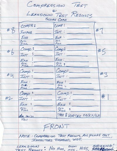
I scribbled up a quick Compression + Leak-down Score Card that I'm hoping that you
will fill out and post the results. (See attachment #1.)
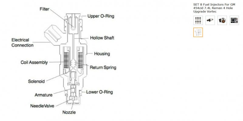
And in Attachment #2 is how I accuratize my observations while performing a careful
leakdown test. You see, the sound of high frequency air hissing can bounce around
off of all the different hard surfaces in an engine bay, leading to my inability to discern
if a low-level leak is from the 454's oil filler tube, throttle body, or even the radiator
opening. (The exhaust pipe is a lot easier...unless of course it's rusted out.)
But when you add the paper towel tube to the testing, and hold it to your ear
while placing the other end in the aforementioned locations, it becomes a no-brainer.
You know, when I ask a shop how did the compression test go, and they say 'good',
all within 15% of each other, with no further details, my head drops a little in
disappointment.
On the other hand, when a different shop has it all written down, and they say
that 6 of the cylinders were reading 175psi, but the remaining 2 were only 155.
And when their observations are written down on a piece of paper, and you see
that the 2 weaker cylinders are #3 & #5, and that they are physically *adjacent*,
well now we have some actionable info. No doubt that there's a good chance that
the head gasket between the 2 weakest cyliinders is on the way out.
The point I'm trying to make is that if you were to take the time to map out the
Compression Test PSI as well as the Leakdown Test % loss on a cylinder by cylinder
basis, and further add precisely where you pinpointed the source of any leaks during
the leakdown test...well then we will really know IF your engine can actually run smoothly
while being fed a emissions-compliant diet.
IF so, then we can go ahead start trying to sort out if you have aged/lazy O2 sensors, do
you have a marginal MAF, what's the true health of the wiring harness, does your
VCM have leaky electrolytic capacitors affecting your A/D converters *or* your
injector drivers, etc., etc.)
Because if you have one or more intermittent/marginal kinda burned exhaust valves
in place, then there's no need for worry about anything in the paragraph above
before we first fix the underlying mechanical issues.
I don't mind a problem to fix, but I hate a mystery. And you've already worked
hard enough on your big block GMT400 that I'd like to help sort this out if at
all possible. Fill out that score card and let us know what you find.
Tag, you're it. :0)
Fingers crossed. Cheers --