How I Repaired Missing Front Bump Stops

Disclaimer: Links on this page pointing to Amazon, eBay and other sites may include affiliate code. If you click them and make a purchase, we may earn a small commission.

Kens1990K2500

One Piece At A Time
Joined
Jul 1, 2021
Messages
226
Reaction score
272
Location
Rhode Island
I’m writing to share my experience on an issue with GMT400 trucks in the Rust Belt. Although it’s a common issue, there’s very little information about it. Maybe because it’s not a critical component, it’s probably something few people think about. I’m talking about … the front suspension rubber bump stop for the lower control arm.

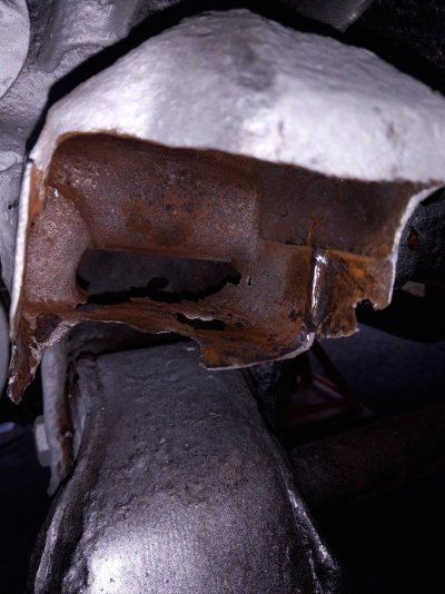
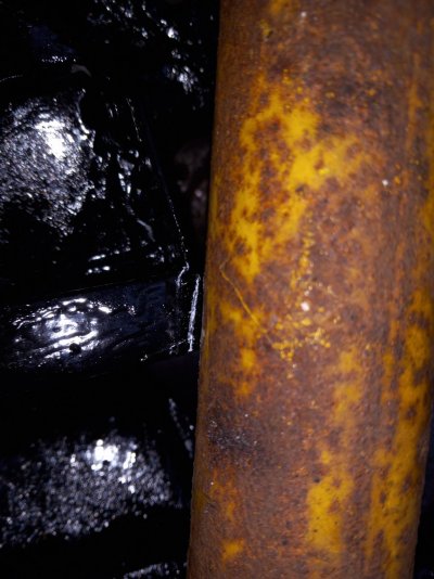
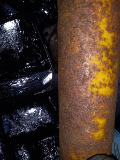
Most GMT400s I’ve seen in the salvage yard are missing them because they rot off (the photo posted below - not my truck - is an extreme example).

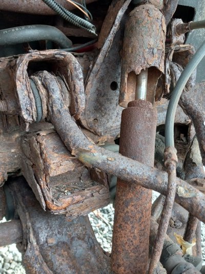
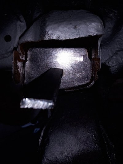
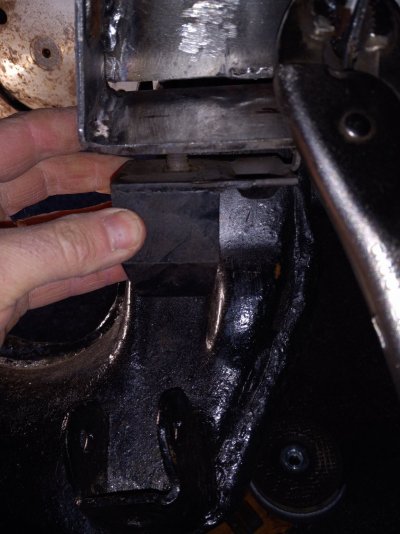
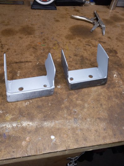
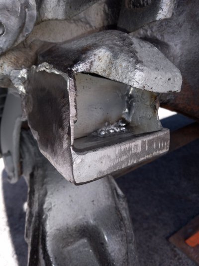
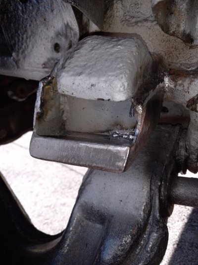
The bump stops consist of a metal plate with a stud, which bolts onto a bracket, which is welded to the frame. In some cases, part of the bracket has rotted away. (The top part of the bracket, whichis where the upper control arm rests when the truck is raised off the ground, is almost always solid, however.)

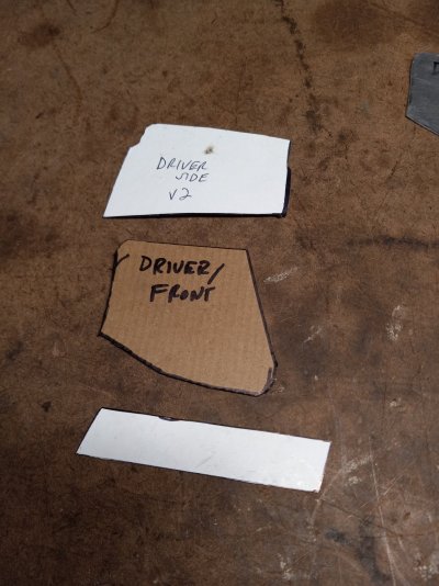
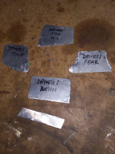
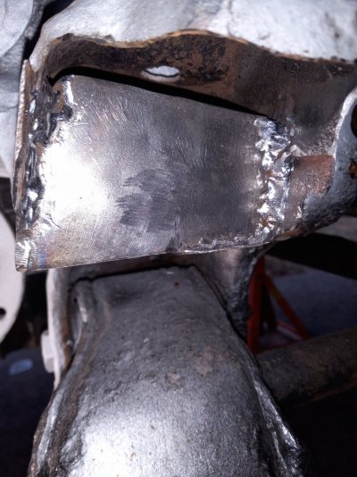
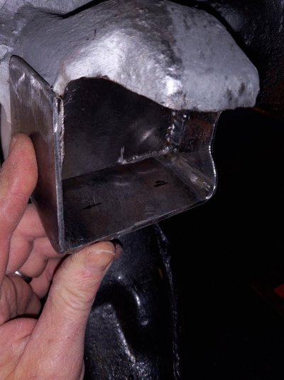
The bottom part of the bracket tends to rot because it collects dirt/road salt/water (almost like a little pool). Like many trucks, the bottom part of my brackets were rotted, so there was nothing solid to mount a new bump stop to. So, metal fabrication and welding is the only solution.

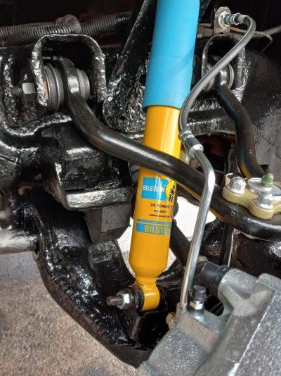
I needed to rebuild the front suspension in my 1990 truck, which had all original ball joints, some of which were very loose and clunky. Once I removed all the worn parts, I decided to repair the bump stop brackets while they were at their most accessible. Some people (most people?) wouldn’t bother, but I’m kind of OCD. Besides, I had bought a Hobart 140 Mig welder and was anxious to use it.

<Note: This will be continued in subsequent, multiple posts or responses, because this is a graphics-heavy write-up, and I can only post five photos per response/post. I'm not sure if there is a better way to format this; please excuse my awkwardness, I am not the most computer literate person.>
 

Attachments

  • Junkyard truck rotted bump stop.jpg
    Junkyard truck rotted bump stop.jpg
    508.3 KB · Views: 29

Kens1990K2500

One Piece At A Time
Joined
Jul 1, 2021
Messages
226
Reaction score
272
Location
Rhode Island
PART 2

My first step was to go to the salvage yard and use a cordless sawzall with a carbide blade to cut out a bracket that was in relatively good shape. This was to have a template or model to work off of, so I could measure/fit/fabricate in my basement, where my tools are, without having to keep going outside to refer to the bracket on my truck. I also used the sawzall to cut out the rotted parts of the brackets on my truck, leaving only solid metal to weld onto.

There is a partition, about halfway back depth-wise, in the bracket. I think this is to add some reinforcement to the bracket. This partition does not go the full height of the bracket, but maybe about 2/3 of the way up. Most of the partitions were rotted on my brackets, so I used the sawzall to remove the rotted portion. You do want to leave at least a trace of them, however, as they are a good reference point when determining depth of the new bracket, and where to drill the holes in the bottom of the new bracket.

After cutting away the rotted parts, the next step was making templates for the new bracket. I decided the easiest way was to overlay the new bracket onto the sides of the existing bracket. Each new bracket overlay consists of consists of five pieces: front side, rear side, bottom, partition and lip. It was easiest to first use thin cardboard to make templates of each piece, because the material is easy to trim. You can use a contour gage to assist with the side pieces, which are curved on the frame side. The other pieces (bottom, partition and lip) are more rectangular and easier to template with the aid of a ruler and angle gage. Speaking of angles, the side pieces do not join to the bottom piece at a right angle. I had bought some square steel stock before I realized that fact. This also means that the lip is not exactly a rectangle, but a parallelogram (remember that from high school geometry?).

After creating templates from cardboard and comparing them to the bracket I liberated from a junkyard frame, I made templates from sheet metal. For steel, I used 1/8” thick steel for the two side pieces, and 3/16” thick steel for the bottom, partition and lip. After tracing the template on the steel, I used a plasma cutter to cut the pieces. I bought a relatively inexpensive plasma cutter from Jegs (model is Cut 40 – I highly recommend it), and it easily cuts curves as well as straight lines (although my straight lines were a bit crooked, since I didn’t use a guide). No matter though, I cut a bit outside the line, and used a grinder to finish the edges. Tip: use a soapstone marker, instead of a black Sharpie; the line will be much easier to see. I also ground the face a bit to prep for welding. Plate steel has a coating called mill scale, which a grinding wheel doesn’t always clean off. The best disc to remove mill scale is Scotch-Brite Clean and Strip XT Pro. I didn’t learn about this until I was nearly finished with the project, so I just made do with my grinding wheel.


<<NOTE: Is there a way to insert pictures in between paragraphs, instead of having photos show up at the end of the text? Like I said, I'm not very good with the computer.>>>
 

Attachments

  • Cut out rot.jpg
    Cut out rot.jpg
    350.2 KB · Views: 14
  • Paper templates.jpg
    Paper templates.jpg
    298.3 KB · Views: 13
  • Metal templates.jpg
    Metal templates.jpg
    397.7 KB · Views: 13

Kens1990K2500

One Piece At A Time
Joined
Jul 1, 2021
Messages
226
Reaction score
272
Location
Rhode Island
PART 3

With my pieces cut and prepped, it was time to weld. Almost. I had to practice with my welder on scrap steel, until I felt (more) comfortable with it. Once I was ready to weld for real, I used vise grips to clamp the front and rear side pieces onto the outer sides of the brackets; there is a prominent seam between the top and bottom halves of the brackets, and this seam is where I aligned my side pieces. I then tacked the bottom piece onto the side pieces, to get the proper angle. Next, I removed the three-piece assembly from the truck, and tacked a brace across the top, so it wouldn’t change the angle from pulling when I welded the full joints where the side pieces meet the bottom piece.

Next, I fitted the partitions into the bracket, lining them up with the vertical seam from the remnant of the old partition. I tacked a ‘handle’ onto the partition, so I could hold and align it while it was tacked in place. Before I welded it in, I primed the back side of it with a zinc-rich, weldable primer from 3M called Weld-Through 2. It’s not cheap at $30+ per can, but it’s a quality product that dries fairly quickly and leaves a consistent coating. I finished welding the partition to the insides of the existing bracket.

Next, it was time to lay out the holes in the bottom. The larger hole is to receive the bump stop mounting stud, and the smaller hole is to receive a tab that keeps the bump stop from spinning when the mounting nut is tightened. I took the three-piece assembly I previously welded, and slipped it over the existing bracket. Mine was a snug fit, and stayed up from friction, but you may need to use vise grips to hold it up.
 

Attachments

  • Divider tacked.jpg
    Divider tacked.jpg
    223.3 KB · Views: 9
  • Divider welded.jpg
    Divider welded.jpg
    374.2 KB · Views: 10
  • U test fitted.jpg
    U test fitted.jpg
    261.2 KB · Views: 9

Kens1990K2500

One Piece At A Time
Joined
Jul 1, 2021
Messages
226
Reaction score
272
Location
Rhode Island
PART 4

I used the divider/partition in the junkyard bracket as a reference point to measure off of to determine the front-to-back depth. I believe the bottom edge of the bracket sticks out a bit farther than the top part of the bracket (where the UCA rests). I used a torpedo level to gage the difference. Slide the new bracket back or forward as necessary. Once the overall depth is set, then you can measure off the ‘partition’ to get your front-to-back center for the holes. For the side-to-side measurement, of the holes, I held the new bump stop against the outside of the bracket, and lined the bump stop with the recessed dimple in the lower control arm. Once I lined it up, I marked the horizontal centers of both holes on the bottom of the new bracket. I then removed the bracket and drilled the holes in my vise.

After the holes were drilled in the bottom, I welded the lip to the bottom piece, and the side pieces. I welded the lip inside and out, and then used a grinder to smooth/round the outside corner welds. To clean up the inside corner welds, I used a pneumatic die grinder with carbide burrs (Harbor Freight sells a set for around $50, on sale – they work well, but I recommend wearing gloves, unless you enjoy metal splinters).

I used weld-through primer on the new and old brackets before I did final placement of the new brackets, over the old. I did a few tack welds, and I also had to bend the top of the rear/side brackets inward slightly, to fit tighter against the contour of the old bracket. I welded along the top seam and back seam of the side brackets, and also welded part of the bottom piece to the partition piece. I did not weld the entire seam between the partition and bottom piece, so water can drain (still, I would recommend flushing this area out well if you live in an area where road salt is used).
 

Attachments

  • Marking holes in bottom.jpg
    Marking holes in bottom.jpg
    281.6 KB · Views: 8
  • Front lip welded.jpg
    Front lip welded.jpg
    345.9 KB · Views: 7
  • Final welding.jpg
    Final welding.jpg
    271.2 KB · Views: 7
  • Final welding 2.jpg
    Final welding 2.jpg
    314.2 KB · Views: 7

Kens1990K2500

One Piece At A Time
Joined
Jul 1, 2021
Messages
226
Reaction score
272
Location
Rhode Island
PART 5

With welding and dressing of welds complete, I re-primed and then painted with KBR Rust Seal.

When I went to put my new shocks in, I noticed that the front lower corner of the bracket was very close to the shocks. This is understandable, since the new bracket was laid over the existing bracket, but unexpected. But I just rounded off those corners, and gained plenty of clearance for the shocks (and it actually gave the fabricated bracket a more finished/factory appearance). After touching up the grinded area with more paint, I bolted on my new OEM bump stops (as of Nov. 28, 2022, these were available on Rock Auto for $50.79 each, but I'm told they are currently out of stock, according to another forum member). Overall, I’m pretty pleased with the end result, but it was very time consuming, and probably took more time than the rest of my front suspension rebuild.
 

Attachments

  • Before shock clearance.jpg
    Before shock clearance.jpg
    267.6 KB · Views: 17
  • After shock clearance.jpg
    After shock clearance.jpg
    292.9 KB · Views: 16
  • Finished product.jpg
    Finished product.jpg
    377.4 KB · Views: 16

Orpedcrow

I don’t know what I’m doing
Supporting Member
Joined
Aug 20, 2022
Messages
2,407
Reaction score
6,105
Location
East Texas
Nice write up! Thanks for sharing!


Hope this helps :waytogo:
Is there a way to insert pictures in between paragraphs,
You must be registered for see images attach
 
Top