As mentioned earlier, at first glance, for the top 4 codes you either have 4 open wires in a
wounded harness, -or- for whatever reason the ECM and the engine do not share a common
ground plane, causing all 4 signals above to read open, even though the individual wires in the
harness are actually good?
If we can figure out a way to use one of the sensors to prove/disprove itself, and THEN see
if that
same measurement is present at the ECM (with and without moving the multimeter's ground lead) then we
can prove/disprove the wiring harness theory for at least one signal...and give us a hint about the
other sensor errors?
****
So as not to make this too long to read, here is what I propose to do as a quick first pass to figure
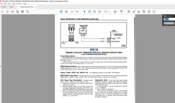
out which way to go, using the Code 15 failure, where we can set a baseline using just an ohmmeter.
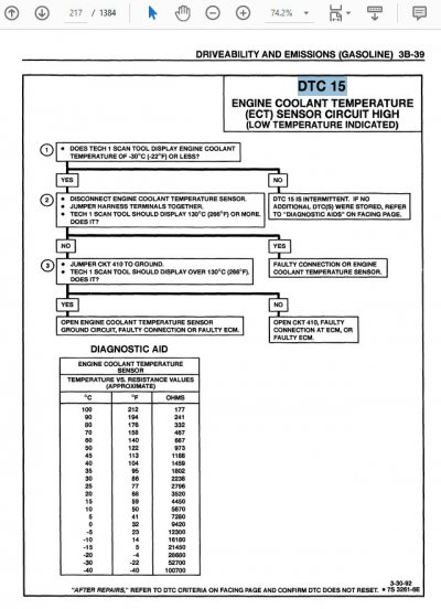
1) On a cold engine that is resting at ambient temperature, use an ohmmeter to measure the
resistance of the Engine Coolant Temp sensor. Write it down, and compare it to the temperature/resistance
table on the 2nd attached page. Q: Does the resistance reading translate to within 5° of the actual
ambient temp? Let's assume Yes, and on to step #2.
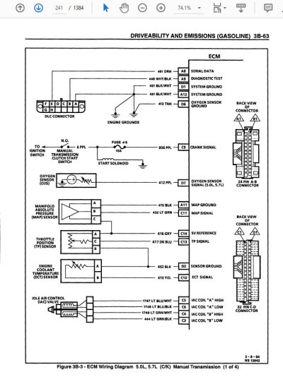
2) Referencing the first attached page, go to the ECM pin/cavity C10 and see if you get the same reading?
NOTE: Make the first reading with the ohmmeter's ground lead in the same spot as when you first tested
the sensor in step #1. Same reading? Now move the ground lead to the ECM and repeat your measurement.
IF the reading is now open (old infinity, now 'OL') then we have a ground issue.
To recap, the 3 possibilities are:
1) Sensor fails check. Either internal open or shifted calibration. Replace sensor and retest. (Sensor as perpetrator.)
2) Sensor measurement passes check at sensor pins. But different measurement on ECM side of harness. (Sensor as victim.)
Find/Fix harness open, then retest. (DTC 15 = open. DTC 14 = short.)
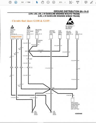
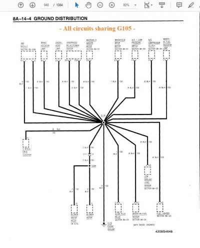
3) Sensor and signal wire good. But after moving ground lead from engine to computer ground signal now out of range.
Fix ground between engine & ECM & retest.
****
Once we get this straightforward/linear/common sense sensor to communicate properly with the ECM, then this will at
least give us a solid spot from which to start troubleshooting the other sensors.
IMPORTANT NOTE: There are a some failures that we can can use DTC codes and a multimeter
to troubleshoot with. On the other hand, a DC multimeter is useless on something like the O2
sensors toggling in real time. When you start to hear that you need to see the 'live data' in order
to proceed, you really will need to do so.
But at this time you have so many codes kicking that I'm hoping that it's a single global error that we
can find, and it will fix most of what's on your plate.
One last thing. We recently troubleshot a no-start/barely-start condition back to an actual failed
ECT sensor. If you would like to see how that played out, go over here and read through this
thread: "
Truck won't start, need suggestions"
To summarize, I picked the easiest sensor to measure/fix. My hope is that the underlying problem
identified by this fix will take care of the majority of the remaining codes. (Assuming that the other
new parts meet specification.)
Let us know what you discover.
Best of luck keeping another GMT400 on the road.
Cheers --