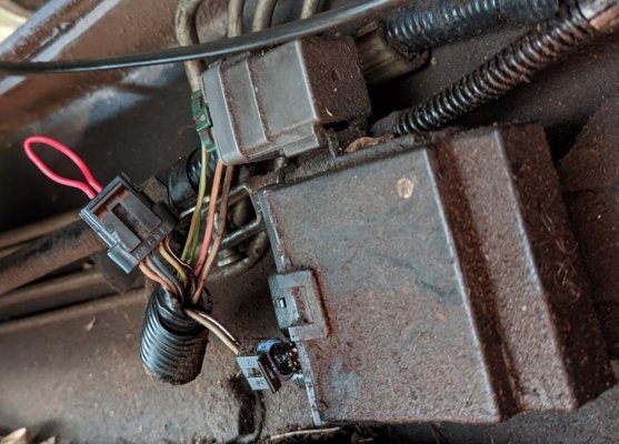
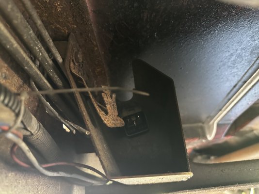
I know I am reviving a year old topic but I am new here. Im trying the search option but not coming up with much. I just purchased a '96 CDLB Dually. Truck is very solid Texas truck up here in PA so it's a rare score but I am finding it to be a wiring nightmare. I'll be asking a bunch of questions around this forum but the relevant question here is... I know my fuel tank is replaced, it appears it originally maybe had dual tanks. Tucked inside the left frame rail before the tank, near the filler is a little box/skid plate type thing that houses a bracket. On that bracket is a clip for something that doesn't exist anymore and a large relay with 4 wires going to it that are completely cut. I do not even see the vehicle side of the cut wires, just the relay side of them.
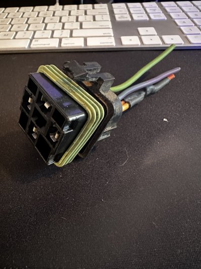
My educated guess is that this is a balance relay. Correct location, correct type of part, but the wire colors do not match up. I am attaching some pictures of the "pigtail" that was plugged into the relay and the location I am talking about. I THINK my fuel gauge works but I have only driven it once (needs a transmission) and it was nearly full. I do not know what the gauge will do as it comes down lower.
You guys have any insight, the wrong wire colors for everything I find it baffling me.
(Insert yours truly emerging from rabbit hole here)
OK
@Brian71583, a quick glance at this thread & I dove into the '99 Service Manual, since the '96+ GMT400
OBD2 electrical architecture is 99% the same? Got done with that, and then realized that there *is* one big difference between the
OP's '99 and your '96. Your truck has your fuel sending unit signal wired straight to the gauge,
not to the VCM.
Phooey! :0)
Proceed to Download both of the '96 Manuals, but I couldn't find the Electrical Wiring section inside either one? Thought I read
somewhere that this might be because a third manual was part of the package back then, and was a known hole in our '96 .pdf cache?
Fudge! :-/
And then someone else working a different issue stated that using the '97 Manuals was a good work-around for '96 Electrical issues?
Pulled those down, and sure enough, I was able to find the Theory of Operation for the fuel quantity indicator system as well
as the schematics to follow.
Yes!
****
It is said that a picture is worth a 1000 words. If your '96 truck came equipped with dual tanks,
then everything to the left of the orange line is what you (are supposed to) have.
Conversely, what little is to the right of the orange line is what single tank trucks have.
Hint: It's ONE wire.
* Lowest reading is ~4 ohms = empty tank.
* Highest reading is 90 ohms = full tank.
* Shorted wire = false empty tank reading.
* Open wire = false full tank reading.
Simple is good. Please note that both the single tank & dual tank
configurations wire up to the
exact same spot. (Since the vast majority
of trucks sold were of the single tank variety, part of the job of the Fuel
Pump Balance Module was to make the dual tank setup transparent/compatible
with the stock fuel gauge. (!)
'97 Chevrolet Light Duty C/K Truck Service Manual
You must be registered for see images attach
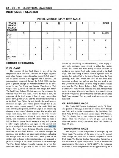
(NOTE: This page feeds into the instrument cluster on p.
8A-81-0)
And here's the Instrument Cluster page -- look for the Fuel Gage & arrow from p. 4
You must be registered for see images attach
****
Reading between the lines above, the reader may have gotten the impression that if the 2nd
tank has been removed, then I would prefer to prune back all the
Fuel
Pump
Balance
Module
wiring. Affirmative. Because we can. And more importantly, this will make any troubleshooting
down the road 10x more intuitive. Let me explain.
FWIW, I've attached the page where the Fuel level circuit's Theory of Operation is discussed.
Why did I include this? Because it explains that IF the FPBM senses an empty/short on
either
tank it will send an EMPTY signal to the gauge. So far, so good.
But guess what the FPBM does if it senses an OPEN on
either tank? It decides to again send an
EMPTY signal up to the fuel gauge. Phooey! With the no-nonsense single tank/single wire setup,
a short = false empty, whereas an open = a false full. At least if I lose confidence in the fuel
gauge I still get a hint as to what kind of problem I'm looking for. But if the FPBM senses a
wiring/grounding issue of any kind (or doesn't get power to itself) then it's just a dead fuel gauge.
In English, if there's enough of the harness left over that I can just jumper out the second
tank, that's all well & good...until I get an open...or short...or loss of power sent back to the
FPBM...or the FPBM itself fails? Then the gauge just dies.
But if I prune all that nonsense out of the fuel gauge circuit and revert back to single tank/single wire
simplicity, then not only do the chances of failure go down, but any troubleshooting down the road
becomes much friendlier & more linear IMHO.
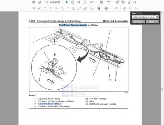
Let's end this on a simpler note. The last attachment shows the physical location of the FPBM,
the relay, and assorted bits for your viewing enjoyment.
****
Apologies for the length, but once I got into the whole "To Jumper, or Not to Jumper,
that is the question" thing I had no choice but to explain why pruning all that dual tank
wiring nonsense out of there (to match the deleted tank) is by far the best long-term solution.
Best of luck sorting this out. Let us know what you end up with. Cheers --
PS: I tried to make sense of the color coding of the wires you took pictures of, but as you can
see in the schematics things weren't matching up.